
Rich Ackermann
-
Content Count
362 -
Joined
-
Last visited
-
Days Won
30
Posts posted by Rich Ackermann
-
-
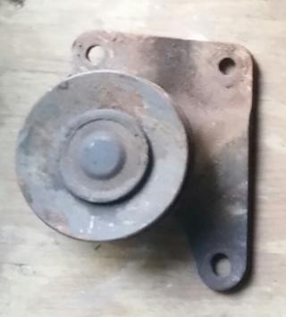
17 hours ago, Mach1 Driver said:The stock AC has an additional idler pulley on the drivers side, and I'm not quite sure why its there. It doesn't route the belt around anything. Maybe the long run of the belt from the crank to the AC makes the belt flap around if its not there?
7 hours ago, aslanefe said:Yes, without that idler pulley the belt flapped around with the original York style compressor before I changed to Sanden. With Sanden, I do not need that pully.
You both referring to this one picture below, the second non-adjustable idler pulley,...correct?
Did it flop around with the York Clutch engaged, or disengaged, or both? Just curious as I have a factory setup on my 73 Vert with a 351C and a York Compressor, but I never reinstalled this second pulley. I have never charged the AC system, so the clutch wire is disconnected. With the York style clutch (permanently) disengaged I don't see a flopping issue without the second pulley, so I now wondering if the flopping happens primarily when the clutch is engaged and under load?
What do you think...?
-
9 hours ago, RPM said:That's a really good looking undercarriage there Rich.
Thanks Bob!
-
4 hours ago, lalojamesliz said:Do you guys think a 3" aluminum driveshaft is strong enough or should I look for a 3.5"?
My engine dynoed at 514lb-ft
I haven't checked the yolk size on my trans yet. If it's not a 1350 I wanted to switch to one. It should be already.....
It's supposed to be built but I have no way to verify. 4r70w bought used a few years back. Big gamble but I wasn't thinking straight at the moment
I would go with a 3.5" Dia for sure.
lalojamesliz reacted to this -
On 12/23/2014 at 12:52 AM, rodbrady said:I just ordered Foose F104 Legend wheels - 17x8s front and back. I'm looking for suggested tire sizes that will fit without modifications.
I have US Mags Bandit 17 x 8 rims in back with a set of Nitto 275 x50 ZR NT555 G2s. I have new Eaton Stock ride height leaf springs. They fit well, but I did have to roll the rear fender wheel lip in across the top from about 10 to 2 o'clock to eliminate any contact with the tire side wall. I also as a precaution trimmed the outer lip on the rubber axle stop mounting bracket to eliminate any sharp edges from contact the inner side wall of the tire.. I watched over time as the car's ride height and fender clearance settle down from a light weight rolling chassis to a fully load car ready for the road.

-
I have a 408 Cleveland with a Tremec TKO 500 5 spd that I bought from MDL. I have an Eaton True Track anti-slip with 3.70 gears and Yukon (N case like) casing. The Tremec and the Yukon have 1350s. When pushing 500+- HP, MDL recommended the following (custom built) driveshaft... It was not cheap, but then again neither is the cost of repair should one blow up as a result of under sizing it.
Aluminum Driveshaft 3.5" tube, 31 spline forged yoke, 1350 U-joints (under 700hp up to 58") High speed balanced
* Drive shaft is measured and built once the transmission has been installed.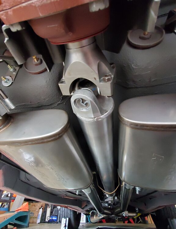
-
At this time every year Facebook sends me a reminder of a post I sent to all a few years ago to start the New Year. So every year since I repost it to help remind me to count my blessings. So I thought I'd share with you these words of wisdom from the one and only C. B. ....Wishing everyone a happy and healthy New Year!

 Mach1 Driver and Caseyrhe reacted to this
 -
3 hours ago, Vicfreg said:Hey Rich, Happy New Year also!!
I got the tail light kit from a company called the "Mustang Project". I am happy with it, easy install, also have it on my '68 coupe. I tested it this past weekend, and they work and look great. You will need a LED flasher relay for your emergency flashers, and they supply the turn signal one that is used to interface with their taillights. It is plug and play.
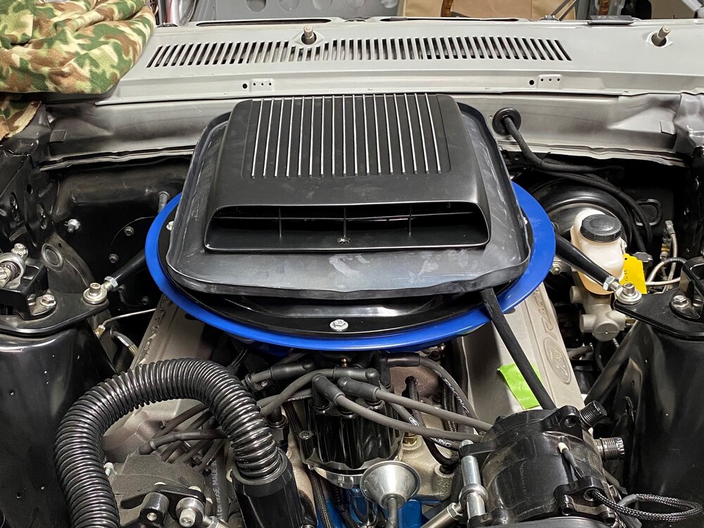
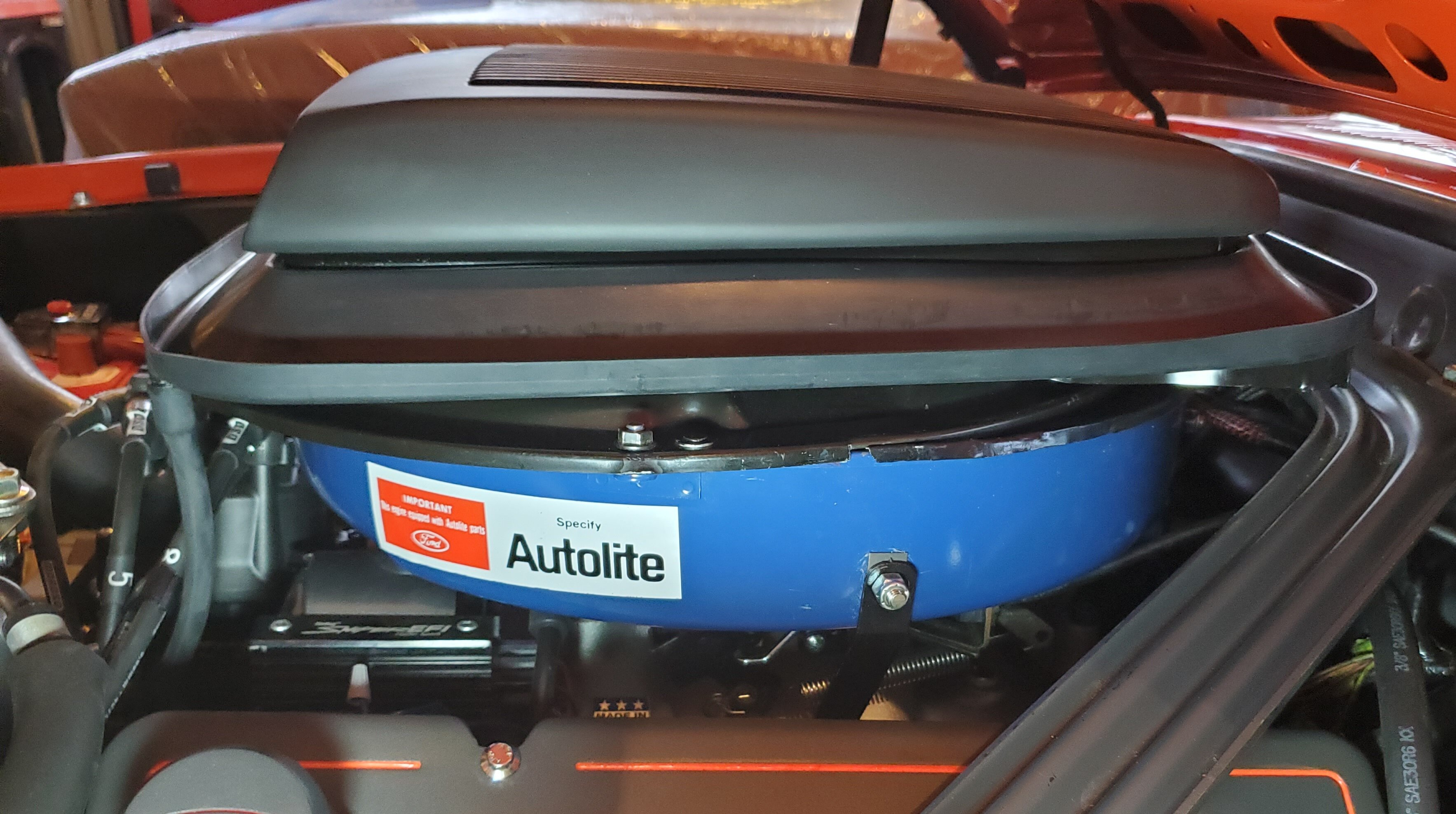
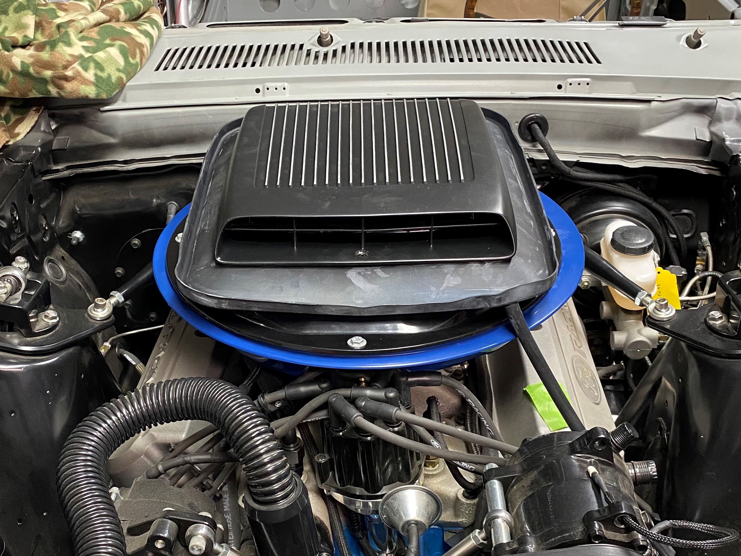
I am happy so far with my fiberglass base. I have not been driving the car, though, waiting on the painters. I added 2 braces/brackets that are attached to the intake manifold, so it seems pretty sturdy, but time will tell. When I was at Carlisle last year, I was on a mission to talk to owners about their shaker setups, and many were running the fiberglass and were happy with it.
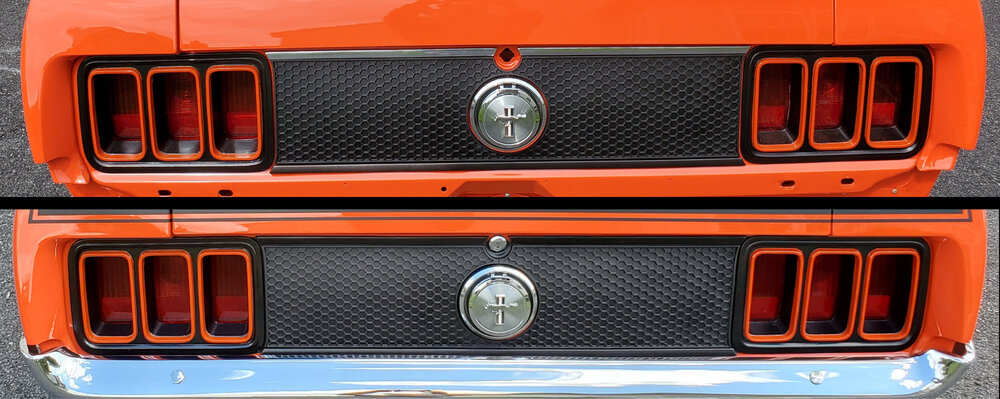
Was going to ask you about any lessons learned/suggestions on installing the honeycomb tail light panel. I have a template, but always want to measure twice and drill once.. My car did not come from the factory with the panel...
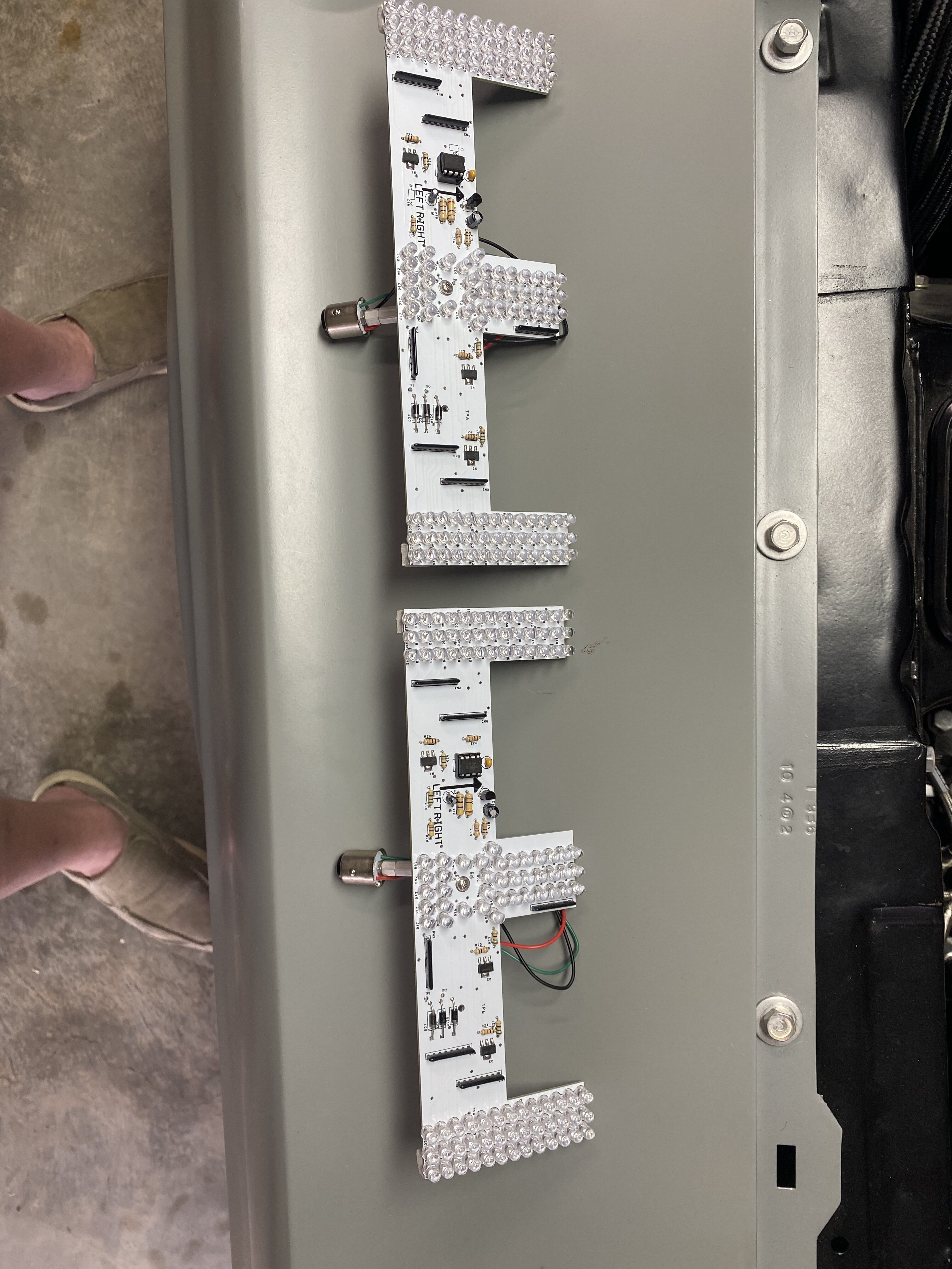
Vic, Thanks. I'll contact Mustang Project. I have been using Red LED rear taillight bulbs, I have been considering going to a sequential setup to match my three sequential LED Arrows I have installed in my side view mirrors. Hopefully I can make them flash together synchronously.
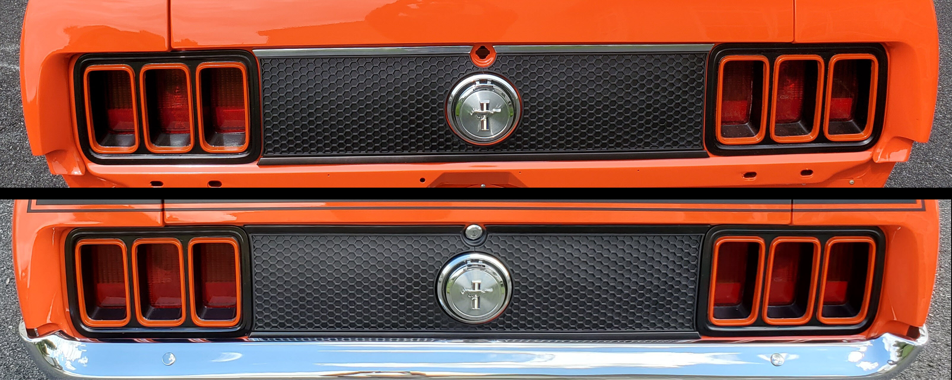
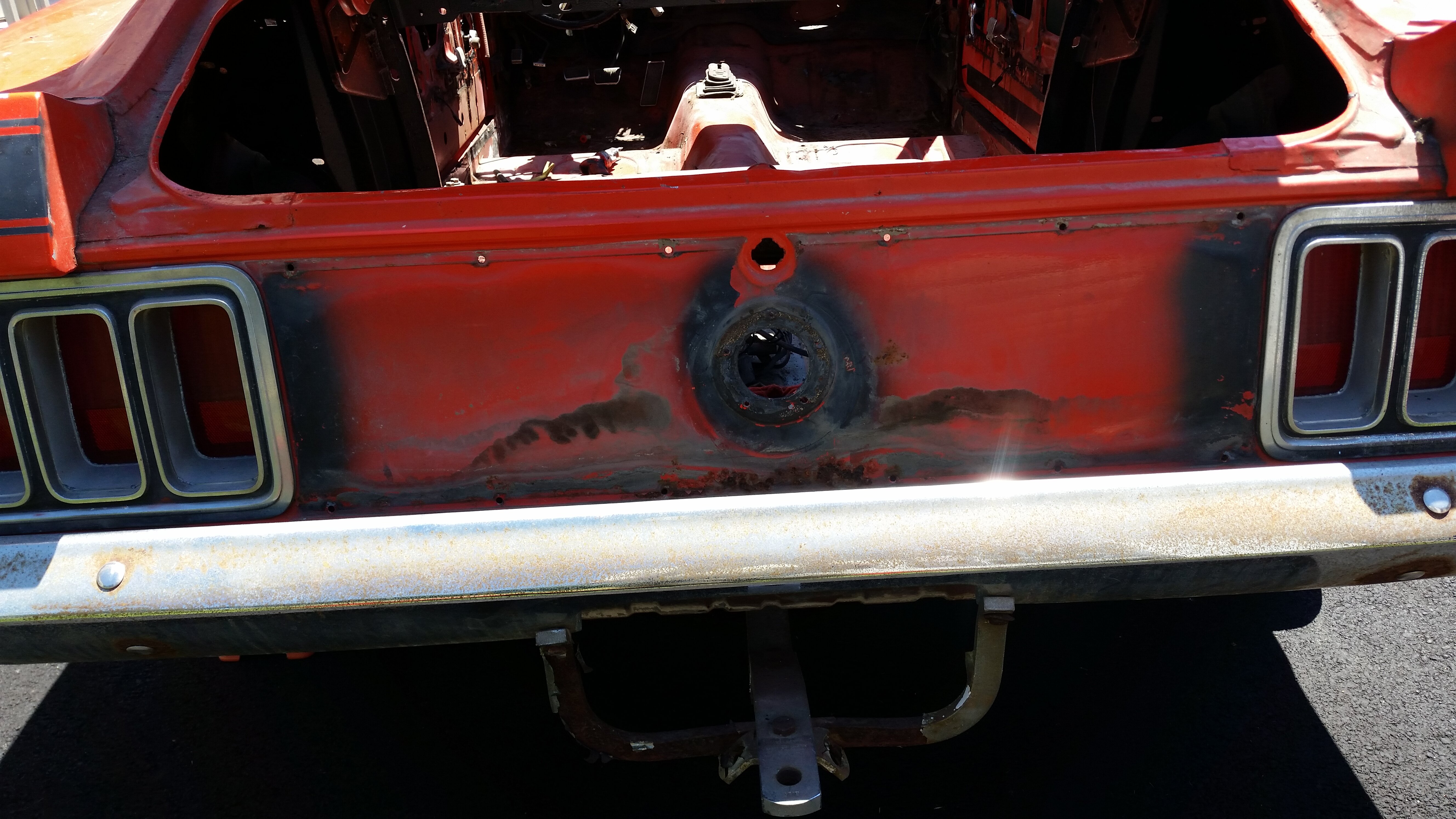
What I did was as follows... Have your taillights, trunk lock, and Gas tank filler tube installed before you try aligning the trim and honey comb panel. First line up the panel around the gas tube flange and lock while centering it vertically between the taillights and attach it there with tape. Then with the attachment hardware (i call them butterfly studs) removed), line up the top and bottom trim pieces with the top and bottom edges of the taillights and confirm they are in contact with the top and bottom edges of the panel and can hold it in place. Now with a marker or tape mark the top edge of the top trim and the bottom edge of the bottom trim. This is also a good time on brightly painted cars to mark off the area between the taillights and the panel, and around the gas filler tube flange and the lock, where the body color show thru between them. For you Vic this is very important step to do with your blacked out taillight bezels. Now remove all, including the taillights, but leave the honey comb panel in place. With the horizontal outer trim marks with marker or tape you made before and the partial screw hole notches on the honey comb panel to position your drill bit, you made you can now drill the top and bottom trim mounting holes. Finally, tape off and paint with a flat or matte black paint those areas you identified where the body color shows up between the panel and the taillight bezels and around the the lock and gas tube flange. Remove the tape when dry and reinstall all of it. You can see the difference it makes with those area blacked out, as Ford did this in the factory as well.

-
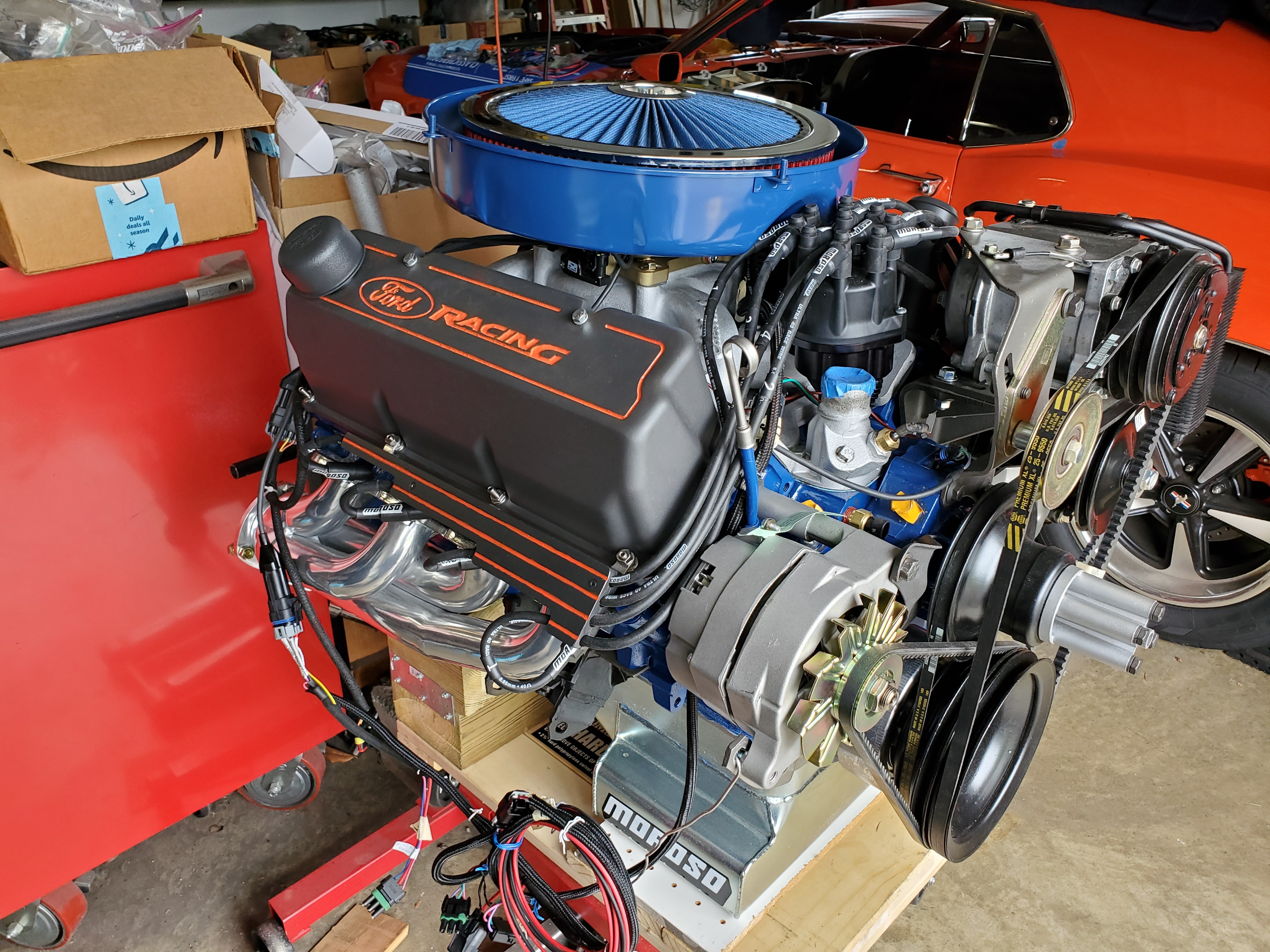
2 hours ago, Mach1 Driver said:Rich, that is a well done and thought-out belt system. All that contact with the crank and alternator pulleys certainly gives it a lot more traction than the stock set-up. I'm curious how well it does when that 140A alternator is at full charge and everything is hot. I think you have a winner there.
My only thought is that the water pump and fan only have about a 1/4 turn of one belt pulling them, and that same belt is driving the PS, but road testing will tell the tale. Have you put any miles on it yet? Please keep us posted.
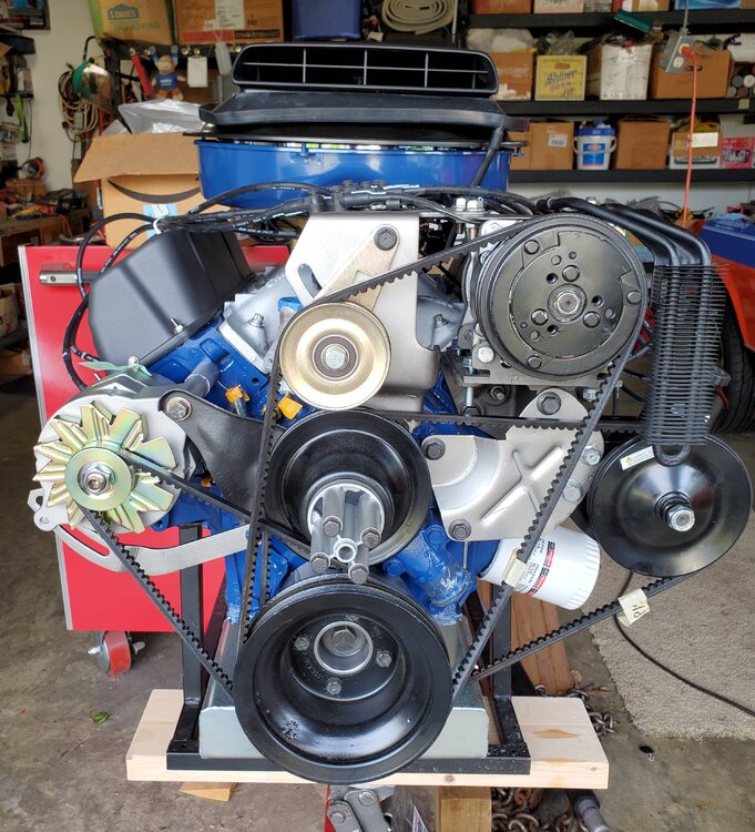
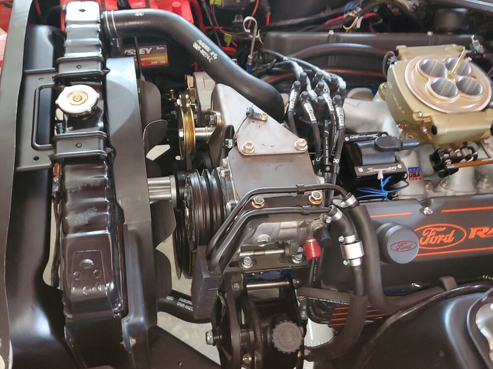
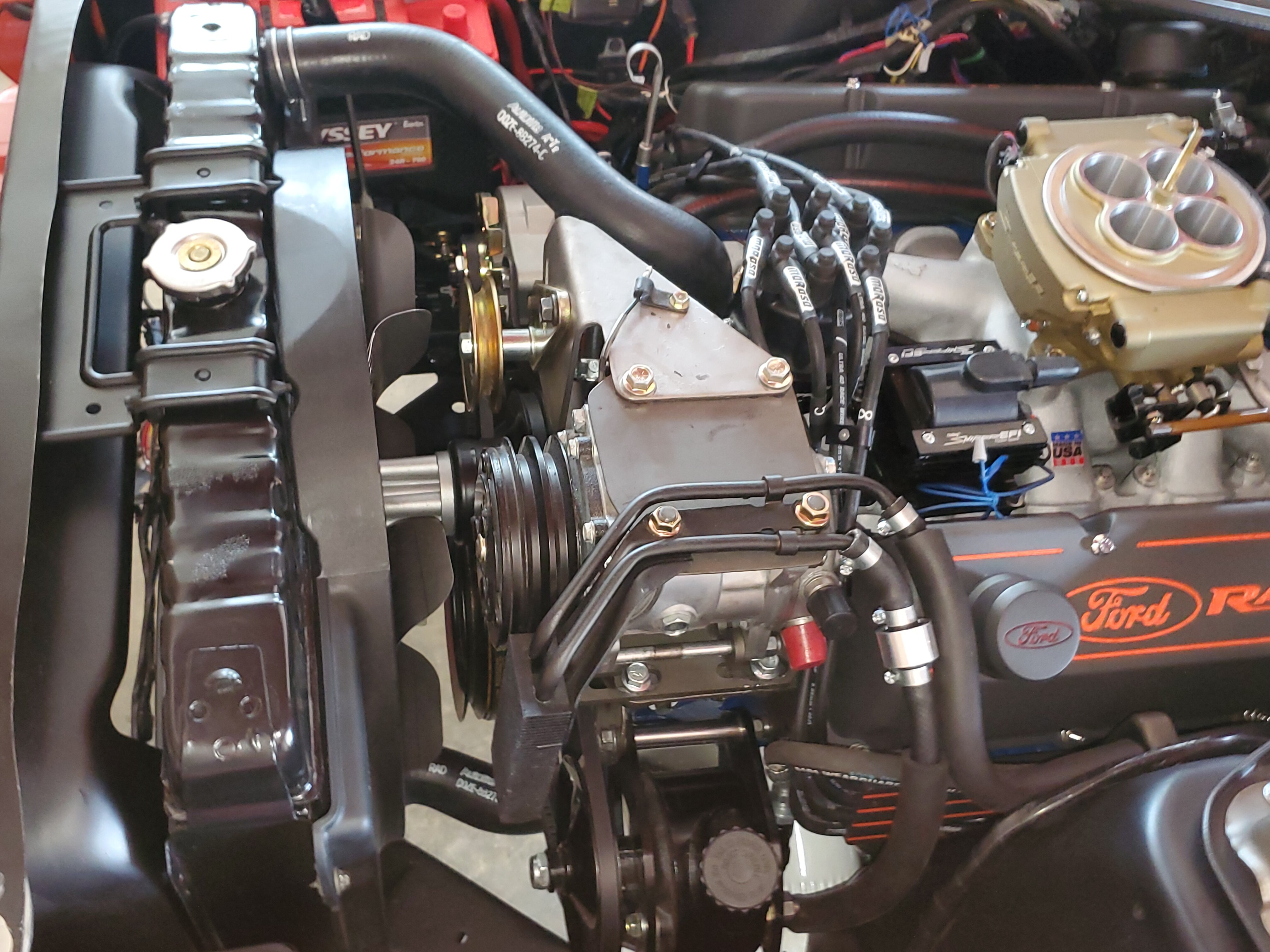
I have been driving the car on the road since October 1st and its been running fine for most part. After a month I experienced some slippage (squealing) on the alternator belt when I would rev the engine quickly, so I tightened the belt a bit more an she has been quiet since. Hopefully it will stay that way. The P/S pump belt width and V angle fit the Saginaw pulley perfectly, but sit a bit deeper than stock in the grooves on the crank and water pump pulleys, but so far no issues. I do feel the hydraulics straining a bit when turning the wheels from stop to stop at a stand still, but that is partly due to the wide front Nitto tires putting more resistance than stock tires. I should mention, That the P/S pressure hoses do not mind bending, but they do not like and flat out refuse to be twisted. To my surprise, I had quite a bit of difficulty finding the right high pressure fittings needed to clock the P/S hoses so I could connect them to the back of the Saginaw pump. I think adding the 71-73 over the A/C compressor P/S fluid cooler will help keep the system cooler when driven hard on those hot summer days.
Overall, I am pleased with the results so far. With the two adjustable Saginaw pump brackets on the front and back and the long 7/8" dia bolt running thru the three brackets and in to the stock accessory hole in the head, they setup is solid and does not flex when tightening up on the v-belt. Very important to square off your pulleys and get them on the same plain as the crank and water pump grooves to minimize resistance and prevent fraying the belt edges.
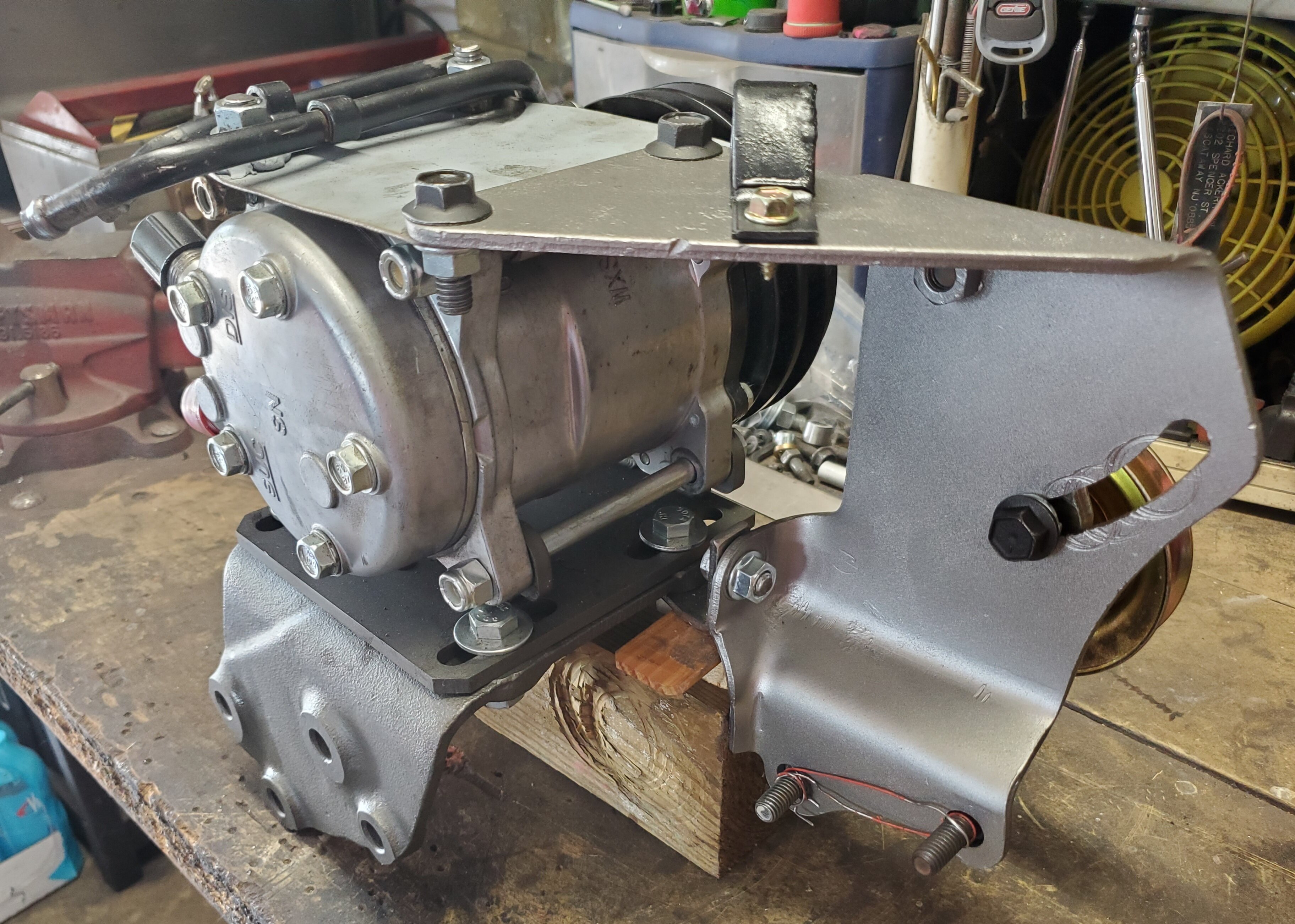
What I have not hooked up and tested yet is the A/C belt, but I don't anticipate any issue there. The belt grooves on the Sanden and the crank pulleys match, and the crank pulley is designed to drive the old York Compressor, but that test will not happen until sometime in the spring. Here are a few more pictures...

 days.
Mach1 Driver and RogerC reacted to this
days.
Mach1 Driver and RogerC reacted to this -
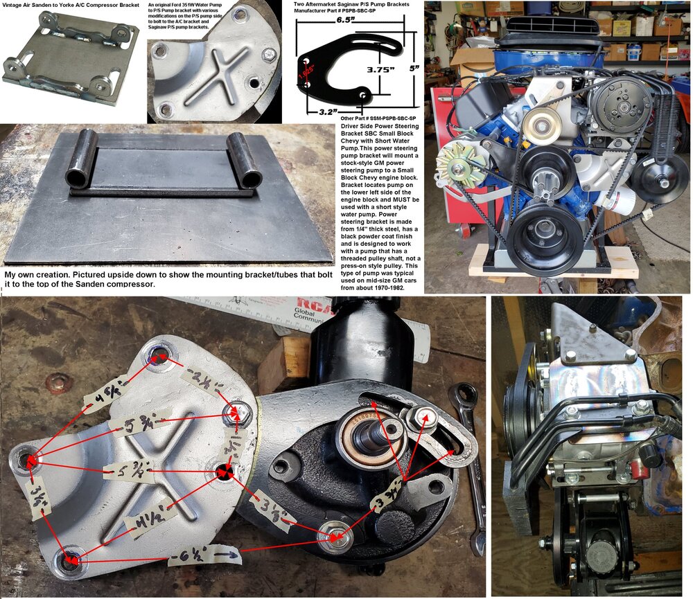
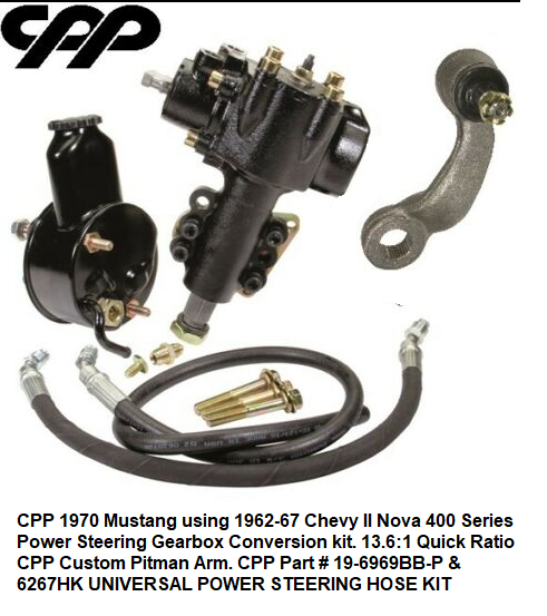
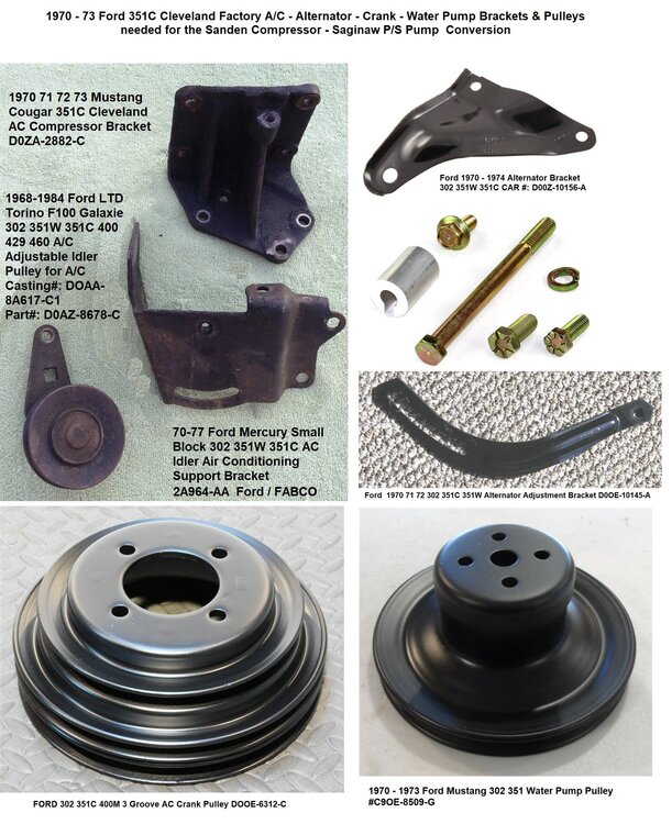
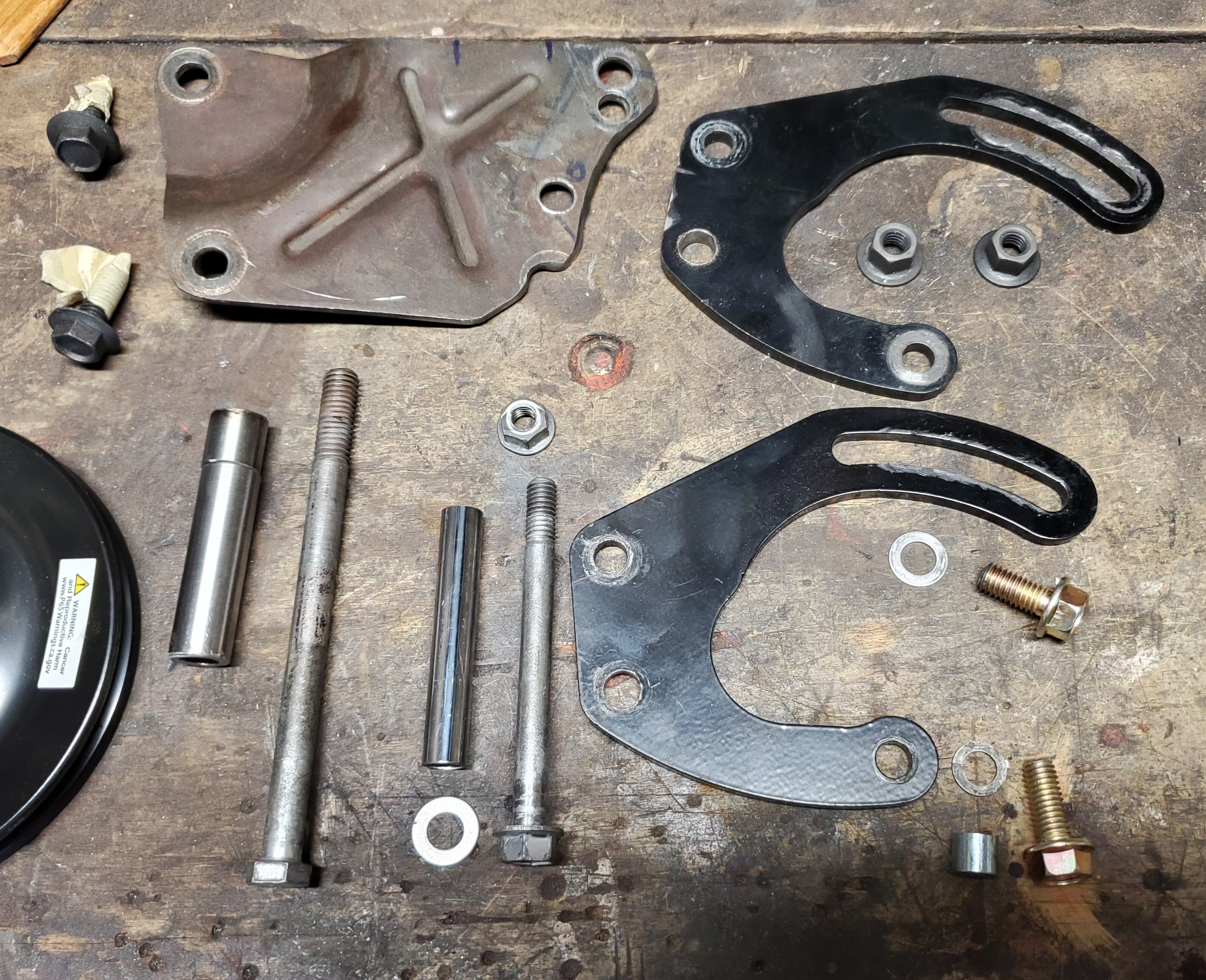
Many (but not all) of the accessories and brackets are the same on the Windsor and Cleveland small blocks. I have a 351C with a Tuff Stuff 140 amp Alternator, A CPP (Borgeson like) Saginaw Powersteering pump and Vintage air Sanderson A/C compressor. There are no v-belt accessory brackets on earth that support this combination. I used a stock 351C three groove crank pulley, and stock single groove Water Pump and Alternator pulleys. The passenger side alternator, brackets, and v-belt are a slam-dunk stock setup. On the drivers side I had to make the P/S and A/C brackets by combing a few stock brackets, a couple of brackets available from the aftermarket, and then I had to make a bracket, modify a couple, and make all the spacers. Finally fine the right side v-belts. PS. I only used high quality toothed Belts. I have read that these belts grip better.
In my humble opinion, to avoid belt slippage/squealing/wear, it is important to have the alternator belt on its own and on the middle groove on the crank pulley and the A/C compressor dedicated on the large outer groove. The Water Pump and P/S pump share the inner most groove. It took me a lot of time and trial and error to make certain all the accessory pulleys were on the same plain with their counterpart groove on crank pulley and also that the accessory pulley was square with the belt and then make the right length spacers. Leaving any angle in the belt forward/back or tilt left/right in the pulley will cause the belt edge to fray in a hurry.


-
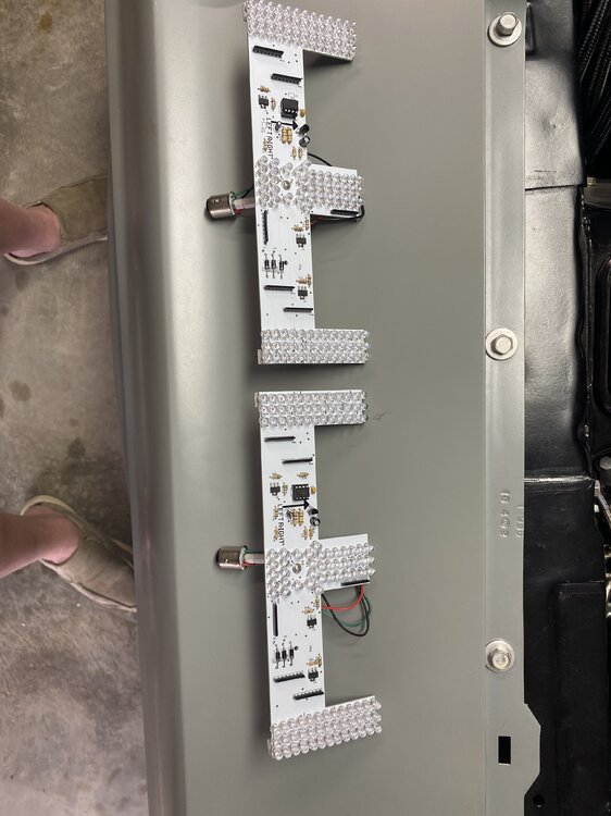
On 12/29/2021 at 6:03 PM, Vicfreg said:Catching up on some mini projects while I’m home for the holidays. I have my LED tail light assembly‘s together, and did some quick checks of my tail light wiring harness, and connections, to make sure everything was working OK.
everything seems to be working well, I just need to get an LED flasher, to check out my sequential tail lights.
You will probably notice my powder coated tail light housings, that’s keeping with my all black trim theme. Should be pretty cool.
Hi Vic, Happy New Year! Where did you get you sequence conversion kit from ? Second question... Do you like the fiberglass Ram Air Base you have? Is made well enough to hold up under the stress from heat and the weight of the ram air stack? I did not go that route, thinking that the fiberglass version may not be strong enough to support the full stack and it could warp with the heat of the engine over time.
Regards,
Rich
-
13 hours ago, Vicfreg said:Nice weather in North Carolina today, so did some painting
Hi Vic,
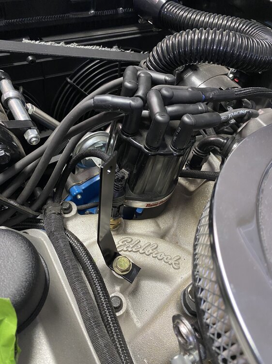
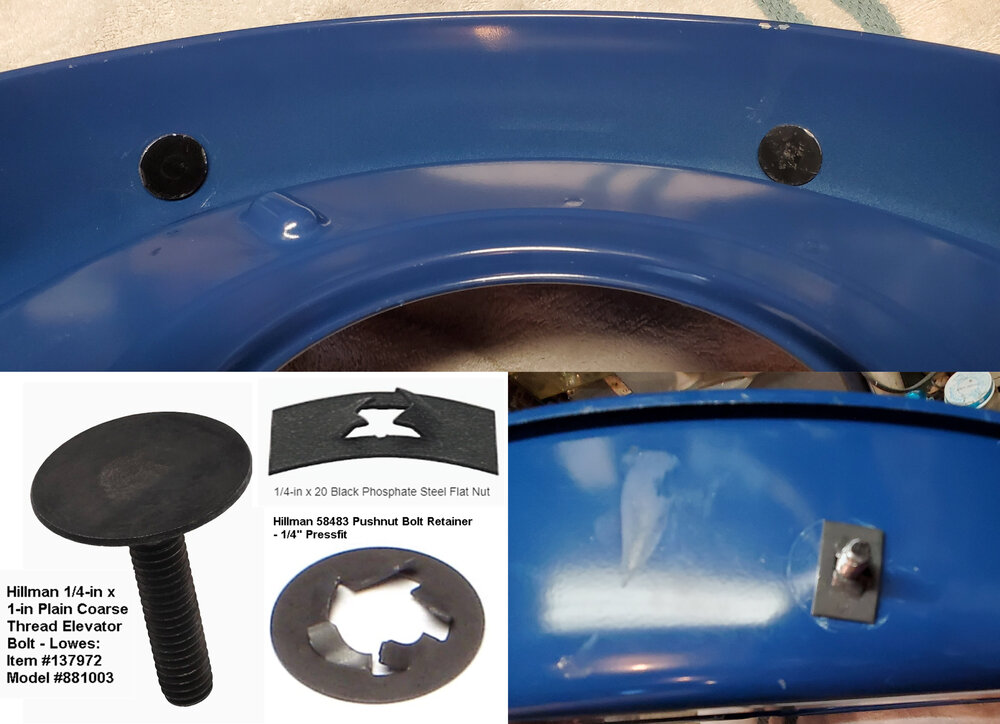
I believe your base is fiberglass. You may want to consider using the same stud I used on my base. They have a large thin flat head so they will cover a large surface for the glue to adhere to and thin enough that they don't cause any interference inside the base. Also I used a press on retainer clip on the outside. Although I used the rect angular press on clip as you can see in the picture, I prefer the round one below as the don't scratch the paint like the rectangular ones do. I used two brackets from my manifold to the base... one straight back at the rear of the base and one about 90 degrees on the drivers side. It maybe over kill, but I was worried about the weight of the shaker stack with all the shaking it does resting just on the Sniper and held down by just the center stud through the lid. The brackets will provide more stability and take the stress off the sniper. The bolt and retainers are from Hillman and I bought them from Amazon or Lowes.
Question: Where did you buy your fiberglass base from? I like to contact them to see if I can buy just the metal offset ring.
Thanks

-
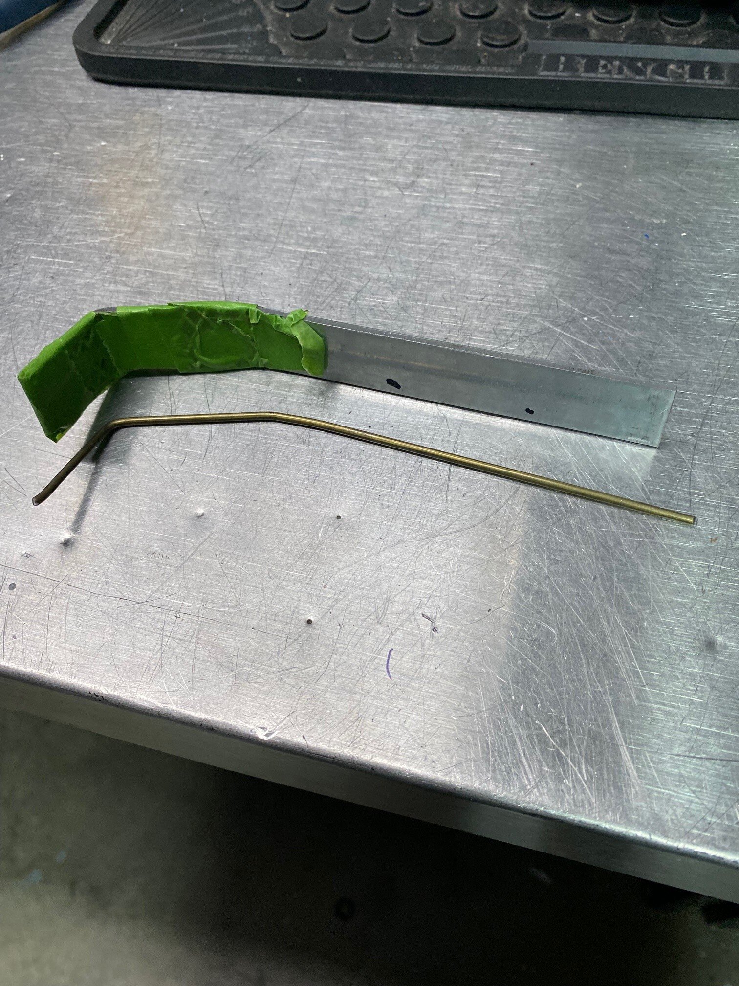
On 10/23/2021 at 10:00 PM, Vicfreg said:I don't have a lot of metal forming equipment in my small shop, so I rely on basic tools and also basic metal working skills to make stuff.
In this case, the local Ace Hardware had some Aluminum stock that was had for a good price.
When I want to make a bracket, I use a coat hanger to bend and re-bend until I get the shape I want. Then I take a new, straight, coat hanger piece and bend it cleanly to match my original prototype. I put my aluminum stock in my heavy vice. I have magnetic/rubber vise blocks, but needing a tight fit, I used painters tape to wrap my aluminum stock to keep from marring the surface.
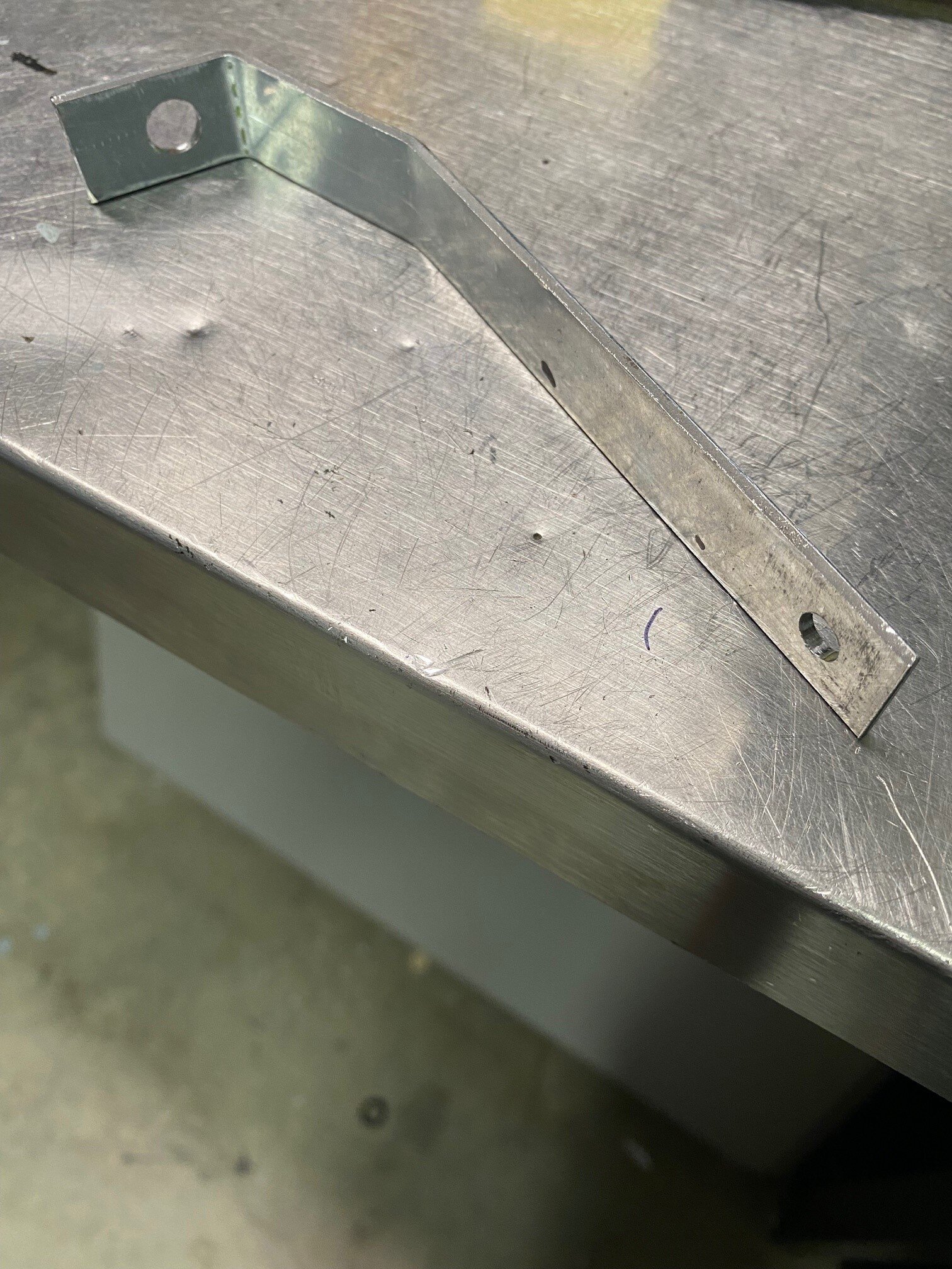
Using an old 8oz Ball Peen hammer (flat end), I carefully work the piece to the angle I want, with the coat hanger mock up next to it. In this case, it worked quite nicely, as you can see.
Then, I marked and drilled pilot holes, verified the locations, and drilled my final holes for mounting.
Inside the base, I will use a 1/4 -20 Tee Bolt and epoxy it in.
Now to use some self etching primer, and paint my bracket.
More to come
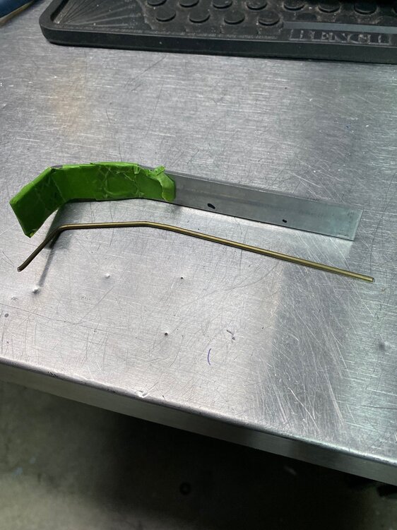

Nice Vic! Aluminum stock is easy to work with. Building a template is important, because you can't bend and re-bend it too many times or aluminum begins to crack at the bends. I use very thin Sheetmetal for flat templates or wire or even pvc pipe for round ones.
-
On 10/11/2021 at 9:17 PM, Vicfreg said:After exchanging some lessons learned with Rich, I modified my shaker to rotate it so that the front indent in the base was correctly oriented to clear my distributor and ignition wires. With my particular base, which is a 351W fiberglass reproduction, I cut the 3 studs off the base, and aligned my shaker top so that it was "straight". I then drilled new holes in the base to align with the holes in the midplate. For now , I will use some 1/4-20 bolts and nuts to secure it. Long term, plan to epoxy some T-Nuts on the base and use 1/4" bolts on top.
More to come.....
Thanks, Rich....
Hi Vic, Always happy to share ideas. Helping each other with our builds is what makes this forum so valuable. It's what we do.
-
1 hour ago, Mike65 said:Congrats Rich, the Mach looks awesome.
Thanks.
-
They look great. Can't wait to see them installed and working.
-
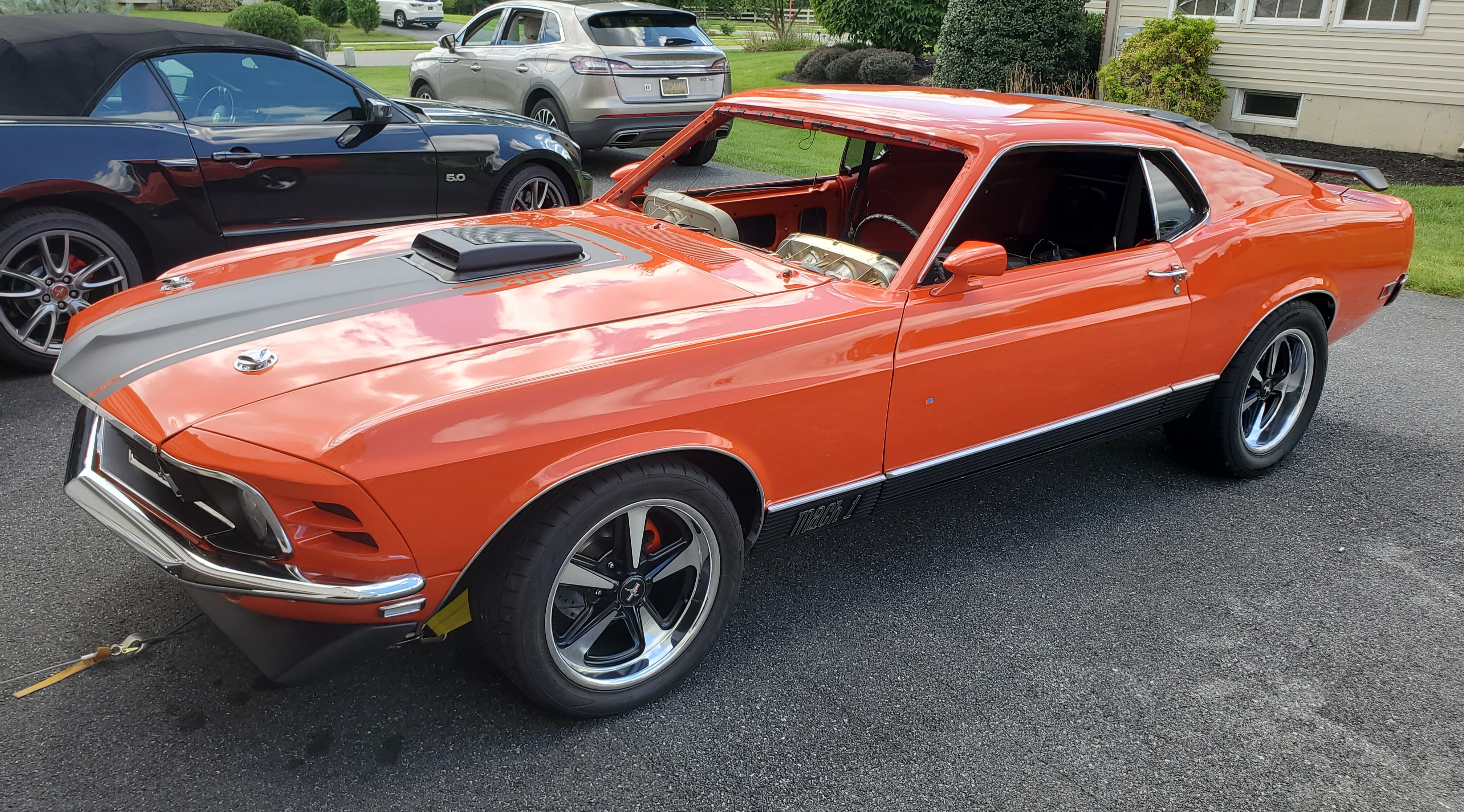
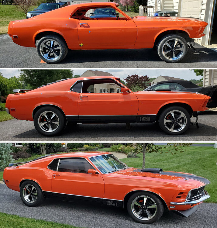
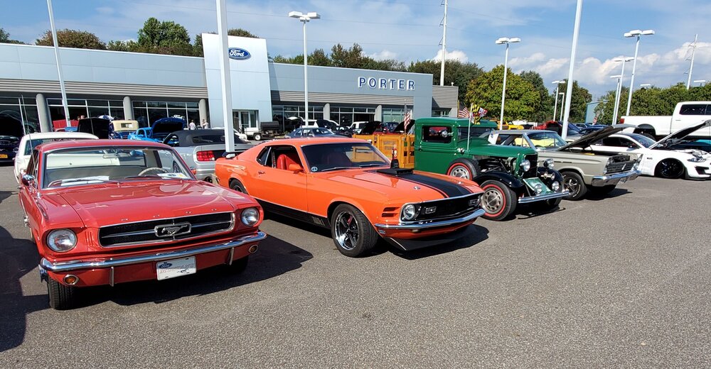
Well, The car is essentially done. Although we all know that our cars are never ever really done! I do have a list of things I need to or want to change/fix or tweak.
I belong to the local Mustang & Fords club here in Delaware and we had our fall show sponsored by a Ford dealership in Newark Delaware, Porter Ford. It was a nice day and we had a great turnout. I took the car to the show where it made it's debut. The car got a lot of attention and took home it's first trophy. The awards were based on spectator popular vote and a Dealers Choice award.
-
2 hours ago, Grabber70Mach said:Your car looks and sounds great, congrats on the journey so far. Hope you get her over the finish line and start enjoying the ride.
Thanks. I am very close to having it pass inspection road worthy. In DE cars newer than 1968 still need to pass emissions. Unbelievable!
Grabber70Mach reacted to this -
On 9/25/2021 at 2:22 AM, STINKY STAN said:Thank you , Rich
You are welcome. Happy to help.
-
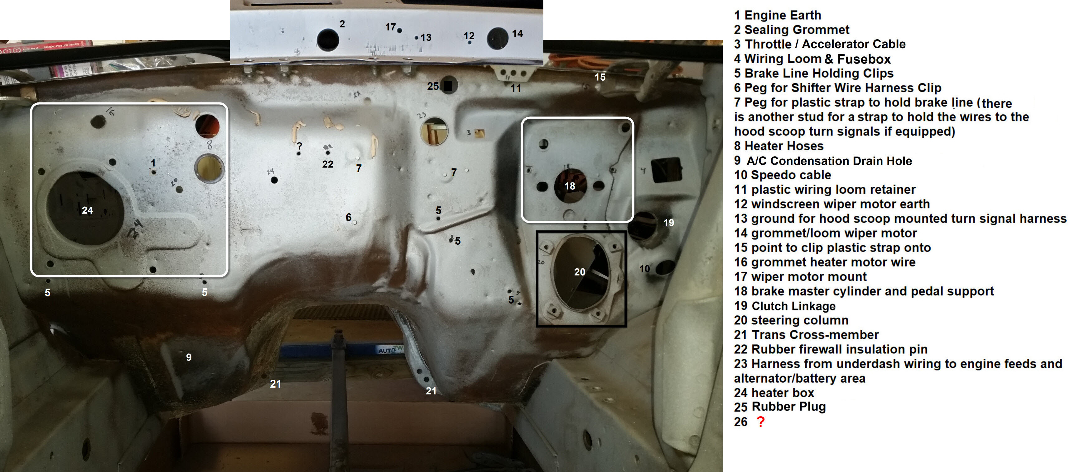
Hi Stan, Welcome to the forum! This may help you with identifying what's on your firewall. It's a picture of my 1970 Mach 1 351C M code with no A/C, no power brakes, no P/S, Manual trans.
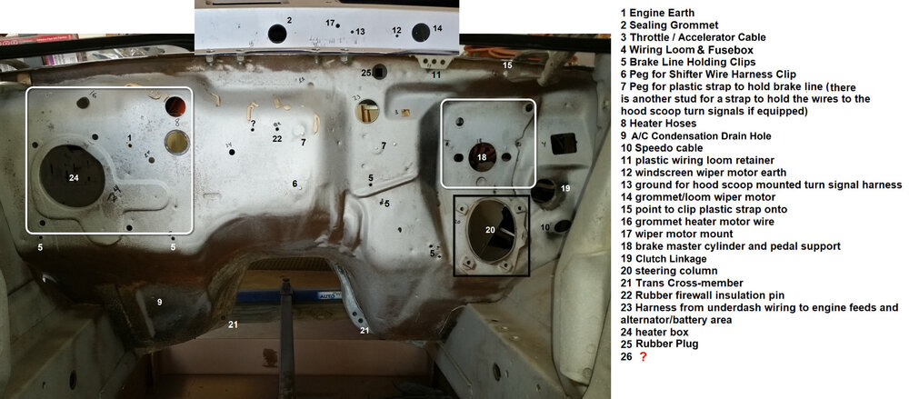 m. This might help you
Mach1 Driver and Jesse 69 Fastback reacted to this
m. This might help you
Mach1 Driver and Jesse 69 Fastback reacted to this -
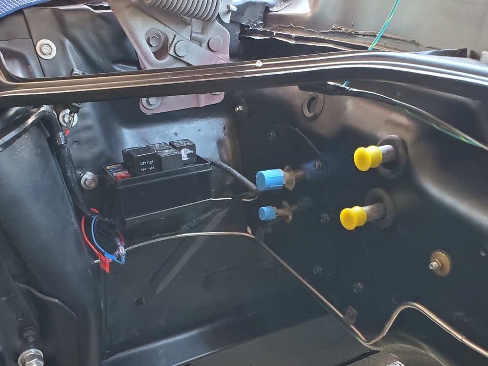
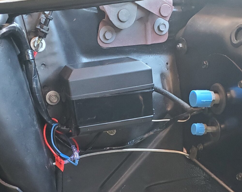
On 9/23/2021 at 1:46 AM, jjstang said:Can you actually get to the relays if needed?? I thought of making some brackets but to squeeze it in on the firewall for access. Just hopping there was a obvious solution I didn’t think of. Thanks for the suggestion
If you are mounting your relays somewhere in the engine compartment, I would suggest using a relay box with fuse slots, or use weather proof relays. Here is what I did....
-
46 minutes ago, RPM said:Bigmal I don't have any pics for measurement of my 2 inch drop. I ran a two inch Shelby drop for a while, but you need an upper control arm that has the proper ball joint angle to keep the bj from binding as the oe would do. Me being a crappy driver with no feel couldn't tell the difference between the one and two inch drop.
Back around Y2K when I was looking into the drop, I think the info I got was from a place called Dr Gas out of Utah that made wedges to angle the ball joint for a drop more than one inch. They said that 69s could handle up to a two inch drop, so more of anything is better, right?
I think I've read somewhere that 1-3/8" is the optimal drop. I've since gone back to the popular one inch drop.
For what it is worth, here is the 1" drop template I received from Global West. I wrote the measurements all over it, if you want to make your own. The instruction are simple... Bolt it thru you existing upper control arm shack tower holes and drill two 1/4" holes thru the 1/4" holes in the template below the factory holes..
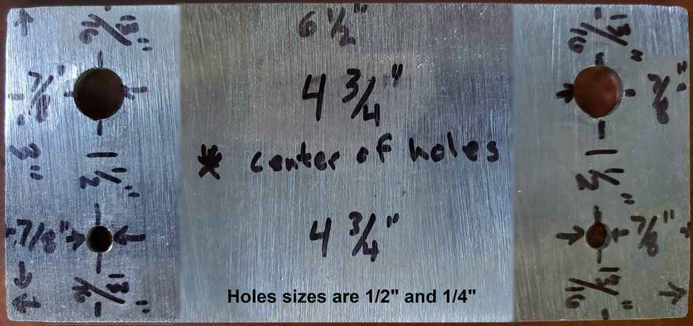
Also attached below are the alignment instructions, if you are using Global West's upper and lower control arms, Strut rods and Eccentric lock-outs...
1967-1973 Mustang Plus 3 Upper Control Arms # MNR-733 (Sold as a Pair)Global West has engineered an upgraded upper control arm for 1967, 1968, 1969, 1970, 1971, 1972, and 1973 Mustangs; the arm provides additional positive caster by moving the upper ball joint back towards the rear of the car.
This particular kit is used for street and handling applications. (Global West also manufactures a control arm for drag racing / street.)
The new Plus 3 Mustang arms are shipped assembled with billet cross shafts, Del-a-lum bushings and ball joints. The a-arms are black powder coated and the cross shafts are blue zinc (silver). Global West manufactures this product in its own facility here in San Bernardino CA.
Tech Information: Caster
With upgraded suspension and present tire technology, caster plays an important part for proper handling of the car. Caster does the following: provides straight line stability, has a self centering action on the front suspension, improves initial turn in during cornering and also resists pulling (right hand drift) caused by road crown.
The Alignment Adjustment and Limitation:
Caster on 1967-73 Mustangs is adjusted by moving the lower control arm forward via the strut rod. The strut rod is threaded at one end where the rubber bushings reside. By loosening and tightening the jam nuts you can pull the lower arm forward gaining more caster.
This was not an option on 1967-1973 Mustangs. The real limitation on how much caster you can get is mainly based on the rim and tire combination you are planning on running. The larger sizes limit how far you can move the lower arm forward because the tire runs into the lower portion of the front fender when the wheel is turned.
If this occurs, you will have to reduce caster, which is not the best answer. Now with Global West Plus 3 upper arms you will be able to get the caster you need!
Global West Plus 3 upper arms have 3 degrees of positive caster built into them. This will eliminate the need to pull the lower arm so far forward in order to get the desired alignment.
Coil Springs are stock height #: s-27 performance street with 640 pounds per inch.Global West has engineered an upgraded upper control arm for 1967, 1968, 1969, 1970, 1971, 1972, and 1973 Mustangs; the arm provides additional positive caster by moving the upper ball joint back towards the rear of the car.
This particular kit is used for street and handling applications. (Global West also manufactures a control arm for drag racing / street.)
The new Plus 3 Mustang arms are shipped assembled with billet cross shafts, Del-a-lum bushings and ball joints. The a-arms are black powder coated and the cross shafts are blue zinc (silver). Global West manufactures this product in its own facility here in San Bernardino CA.
Tech Information: Caster
With upgraded suspension and present tire technology, caster plays an important part for proper handling of the car. Caster does the following: provides straight line stability, has a self centering action on the front suspension, improves initial turn in during cornering and also resists pulling (right hand drift) caused by road crown.
The Alignment Adjustment and Limitation:
Caster on 1967-73 Mustangs is adjusted by moving the lower control arm forward via the strut rod. The strut rod is threaded at one end where the rubber bushings reside. By loosening and tightening the jam nuts you can pull the lower arm forward gaining more caster.
This was not an option on 1967-1973 Mustangs. The real limitation on how much caster you can get is mainly based on the rim and tire combination you are planning on running. The larger sizes limit how far you can move the lower arm forward because the tire runs into the lower portion of the front fender when the wheel is turned.
If this occurs, you will have to reduce caster, which is not the best answer. Now with Global West Plus 3 upper arms you will be able to get the caster you need!
Global West Plus 3 upper arms have 3 degrees of positive caster built into them. This will eliminate the need to pull the lower arm so far forward in order to get the desired alignment.
Note: When using Plus 3 arms, there is now a right and left upper control arm. The original control arms (factory or first generation Global West Negative Roll control arms) are universal.
-
52 minutes ago, Vicfreg said:Ralt962 happy that helped. Post some pics of your install, I am sure others have run into the same problem.
Rich - Yes, welding required to install the panhard bar mount on the drivers side frame rail. The instructions show those details.
Yes, there is room to get the exhaust around the panhard bar and rear anti-roll bar, but requires some measure/bend/fit skills that I just don't have.
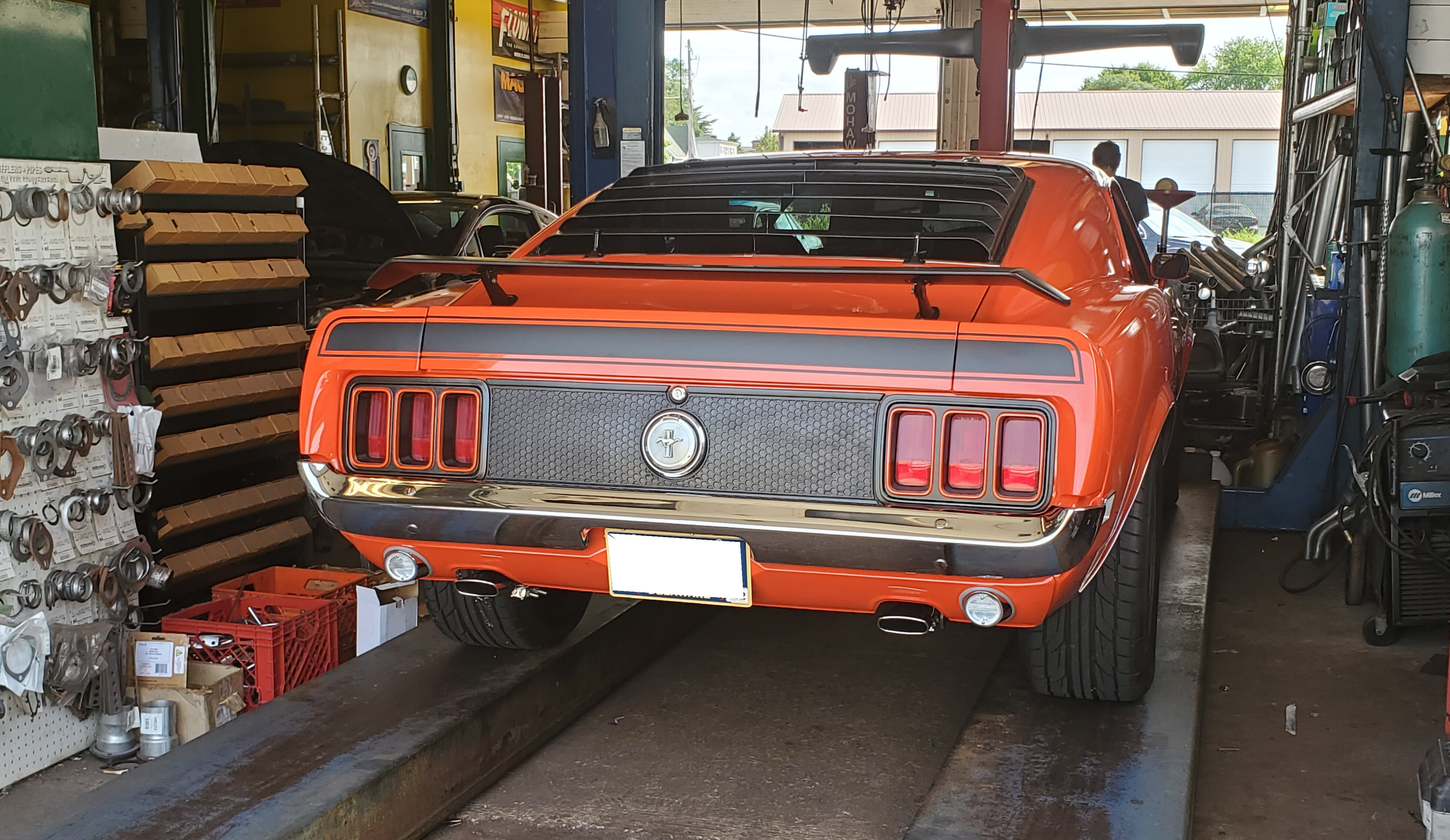
I wanted to run 2-1/2 inch exhaust the whole way back. I also wanted to do something different, so I thought that filling in the reverse light holes in the rear valence, and running the exhaust through the valence similar to a '66 GT would be cool. Came out great. I cannot take credit for the exhaust system "artwork" ....that is all done by my friend Mike (latoracing) a long time member of the forum.
I did all the under the car detailing, but the exhaust is really exceptional. Based on a 1970 "Pypes" 2-1/2 inch SS exhaust kit. As I have a convertible, this was a real challenge as the exhaust needed to sneak on top of the center reinforcement plate on either side of the driveshaft.
52 minutes ago, Vicfreg said:Vicfreg,
The looks fantastic! Very clean looking the the valance. What a great idea...I love it. Unfortunately its a bit too late for me. I have a73 vert so I know what you mean about sqweeezzing those 2 1/2 pipes over the reinforcement plate thru the tunnel.
I used the same Pypes kit on my 70, but with different mufflers. I installed it so I could get the car to the shop and have them fix it and weld it up. Came out okay, but not as up and tight as yours.
My handy work...just enough to get it to the shop...
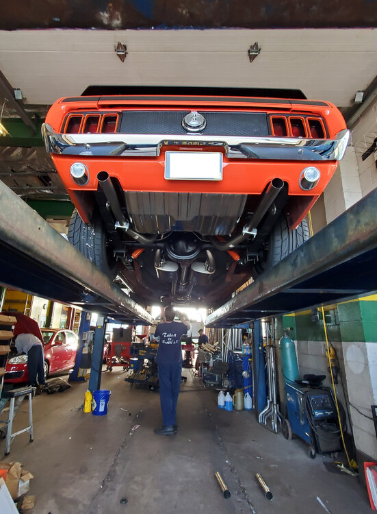
I forgot to get a picture of the undercarriage before they brought it down off the lift.... I do like the factory 70 tips....

-
On 9/20/2021 at 7:29 PM, Vicfreg said:I like it because it is really not a true coil over, as I kept the upper and lower control arms. I wanted the ability to adjust the height of my front end after the car was built, without cutting springs. This is a really slick solution. I can adjust the height of the car literally in 1/4" increments.
I remember looking at that on the Global West website. The upper control arm are has no spring perch, so the strut can just pass thru it. Nice setup.
-
Vicfreg,
Does or will your TCP panhard bar clear stock 2 1/2" dual exhaust? Any welding needed?
Thanks,
Rich


Driveshaft question
in 1969-70 Technical Forum
Posted · Report reply
For health reasons, I avoid using any type of Exploding driveshafts. :-)