Rich Ackermann
-
Content Count
362 -
Joined
-
Last visited
-
Days Won
30
-
-
-
Hi Vic, Thanks for moving tips. We given away a bunch of furniture to friends and family who wanted it. We signed up with a Estate Sale company and they are going to sell or dispose of what we are not bringing, but even with that I have a basement full of stuff, the two cars, and all my tools, and extra car parts to store for about 3-4 months. Any suggestions on short term car storage? We are moving to a retirement community that just open up for lot sales off of Rt64, next to the Jordan Lakes state park (I think it is call) in a old historic town called Pittsboro. We will be near three of our grandchildren in the Apex area. We will be able to see them more often without having to make a 6 hour drive from DE, which makes my wife very happy. Regards, RIch
-
Hi Vic, Your build is really looking fantastic! I really like those horizontal LED headlights. Can you go thru MV inspection in N.C. without side markers on a car made after 1967? In Delaware, I don't you can, unless they overlook it. Anyway, the wife and I will be moving in six months to N.C., about 20 mins southwest of Raleigh. Waiting for the house to be built. I looking forward to living there, but not looking for to making the move. The amount of stuff we have accumulated over the years is just overwhelming. We can it all with us, so what to do? I did not make Carlisle this year for the first time in more than six years. Next year we will have just relocated, so I am not sure if I will be ready to go, but I'll let you know next May. Regards, Rich
-
-
-
Hi Vic, I have been following your build project for a long time, but its been a while since I visited the site, or posted anything. Your Electrical issue is a common problem with the 1970 model year (only), powder coating or not. The reason is that the parking lights and directional signals, which all share the same circuit and same bulbs (with the except of the turn signals in the standard Mach 1 hood), Ford, probably to reduce cost, went from a three wire to a two wire configuration on this circuit. The Ford electrical engineers, got creative and alternated the current across the two wire system. Essentially, on a 1970 model, the ground for each bulb is in series and not in parallel like it was before and after the 1970 model year, which a use a three wire parallel ground system, with the third wire being ground wire. What the two system does is sends 12v positive thru one wire and seeks ground thru the other and then reverses the positive and negative signal. In order to find ground, the system must pass thru each bulb (in series) on it's circuit until it does. Typically ground is found in the turn signal hood ground or under the dash. This passing thru each bulb becomes a problem when a bulb filament or the bulb fixture is failing. Finding the offending bulb can be frustrating. It's like find that one little burned out bulb on that string of 50 bulbs not lighting on the Christmas tree. Ford after seeing the error in their ways, switch back to a three wire in 1971. By you adding a ground wire at the bulb fixture to the chassis or fixture housing, you essentially gave the system another place to find ground. You put part of the ground system back to parallel, where the system can fin ground, in some cases, without having to pass thru a bulb to get there. When I restored my 1970, I added a thirds wire for ground to each light fixture or I replace the fixture with the equivalent fixture from the 1969 model year which was designed with the third wire for ground. So my 70 Mach 1 has a 1969 valence and front and side three wire parking/turn signal light fixtures. The third attachment, I don't know created it, but it was very helpful to me when I was chasing electrical gremilins.
-
-
-
I'll take all, but the complete mirror. Please message me. Thanks
-
 Ford Small Block Toploader Bell Housing C5TA- 8394-A - $125 These Exhaust Manifolds came off my January 1970 built '70 Mustang Mach 1 M-Code. They are a matched set based on casting # (D0AE-9430-G and D0AE-9431-G) and Date Code. They have no cracks or issues. they just need sandblasting and a coat of cast iron paint. If I am not mistaken, they are correct for 1970 and early 71 M-codes and '71 Boss 351,.... $450 + Shipping. Also I will be driving from Delaware to the Raleigh N.C. in late June. To avoid shipping costs, I would be happy to meet you somewhere near the I-95 Interstate and hand you the parts.
 -
-
Maybe you already seen this aftermarket part from Tinman. I just learned of it, so It thought I'd pass it along. https://www.tinmanfabrication.com/products/mustang-convertible-crossover-drive-shaft-loop-1965-1972
-
Very nice!
-
Anybody use the Forel Ford manuals?
Rich Ackermann replied to ThePoose's topic in 1969-70 Technical Forum
Yep.. I"m still old school. My son keeps telling me nobody uses CDs anymore. I slowly have converted many of them to digital on a computer. -
-
Midlife Harness Restoration Status
Rich Ackermann replied to Midlife's topic in All mustang products and vendors
Glad to hear that your his and hers hip replacement went well and you are back to normal..... and fixing those shorts :-). -
-
-
-
Subframe connector installation question
Rich Ackermann replied to ksquared's topic in 1969-70 Technical Forum
Hi Brian, Did you try NPD. If all you need is the two plugs, then this kit may be overkill. PLUG AND GROMMET KIT, (44), repro, contents:377901 seat access hole and top of cowl under fender (10), 376966 front fender apron, trans crossmember (10), 377977 frame rail at sway bar (2), 378923 rear shock access hole (2), 378770 inner frame rails at transmission (2), 377949 trunk floor pan plug above frame rail, side of cowl at door hinge, LH apron behind shock tower (5), 377678 heater hose firewall for A/C cars (2), 377936 inner frame rails at radiator and center of firewall (5), 377356 rear spring front bolt access hole (2), 383181 top of cowl under fender (2), 011202 quarter panel drain (2) NPD Part Number : 011136-5K Manufacturer Reference #'s: 376970, -
Anybody use the Forel Ford manuals?
Rich Ackermann replied to ThePoose's topic in 1969-70 Technical Forum
Yes all the time. I have seven of their CDs... Somehow I lost my original 1973 Colorized Wiring & Vacuum Diagrams, but I have a backup. The Forel manuals are good for Electrical and Vacuum details, and another CD with Parts and body illustrations, but to my knowledge, Forel does not have Engine Assembly. You have to get the shop manuals for that and other things. I have the Shop Manuals from David Graham Auto Literature. Forel also has on CD The Ford Master Parts Catalogs (MPAC), which are packed with parts and numbers by year, model, etc, but are very cumbersome to browse thru, best to use the PDF search function. Finally, there Assembly illustration manuals published by Jim Asborn. There are also helpful, but the pictures are sometimes very faint and hard to read. I prefer a digital copy so I can zoom in on sections. One more comment on Forel, years ago Forel required you to install software called PDF OwnerGuard License Manager to install the CD on you r computer. This software was always malfunctioning and preventing access to the manual. I would have to call them to get it fixed, but fortunately they did away with it a few years back. I say you can never have enough Information....:-) -
Subframe connector installation question
Rich Ackermann replied to ksquared's topic in 1969-70 Technical Forum
1970 Mach1 M-code. The bracket is where the rear brake hardline connects to the flex hose to the rear axle. See picture below. The circular plates are threaded reinforcement plates for the rear seat belts (bucket side) I am not sure what ou are asking here... The frame rail holes for the forward leaf spring bolts. Rubber and push in plugs? -
-
Subframe connector installation question
Rich Ackermann replied to ksquared's topic in 1969-70 Technical Forum
Did my tinman connectors while the car was on the body cart. I would not do it the way I did on a convertible since there is a lot of body flex, but on a hardtop I had no concerns. Outside of the floor pans and front torque boxes my car was solid and all went well. -
-
-
-
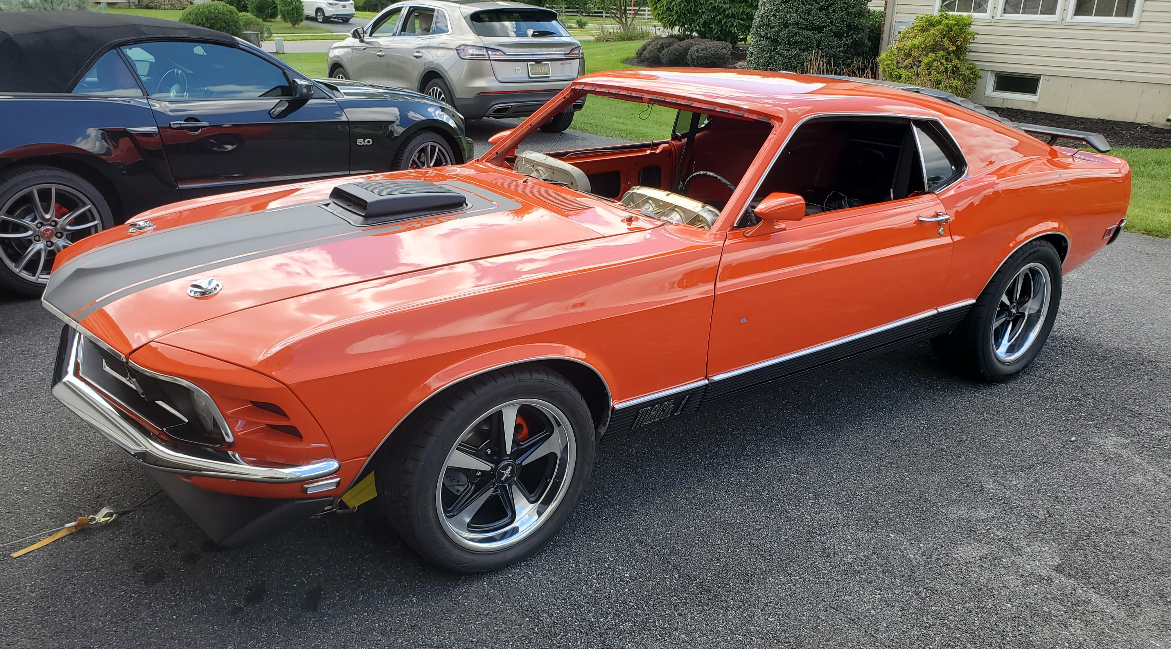
My new 1970 M-Code Mach 1 Project
Rich Ackermann replied to Rich Ackermann's topic in Project Progress Forum
Well...Bob. Okay, I admit, I only drive it on dry sunny days... Mostly to car shows on the weekends, but I enjoy every minute that I am behind the wheel... and that's no bull :-) -
My new 1970 M-Code Mach 1 Project
Rich Ackermann replied to Rich Ackermann's topic in Project Progress Forum
It's been awhile since I posted anything, I've just been enjoying driving the car. While in winter storage, I decided to install a 1" rear sway bar and "CalTrac like" traction bars from CPP. Becasue I converted to rear disc, the factory style sway bars that mounts to the plate that is bolted to the axle/shock plate will not fit around the calipers. So I went with a CPP sway bar that clamps to the axle housing and bolts to the frame near the rear torque boxes. It also does not interfere with the new traction bars. See the captions with each picture below.