
Rich Ackermann
-
Content Count
362 -
Joined
-
Last visited
-
Days Won
30
Posts posted by Rich Ackermann
-
-
8 hours ago, pgold said:So you should have 2 or 3 months to enjoy before the snow start to fall.
July 1987 I was in New York, New Jersey and Washington DC for a wedding and catch up with friends. I had been in Banff Canada for 6 months and couldn't believe how hot and humid it was in NY.
Brisbane have similar temps to you in summer, winters are 5 to 22 C with occasional frosts but none this year. Never snows here. So its mustang time all year round. When we are not in Covid lock down that is.
The Car show and cruise season ends here by November and does not start again until April. July 1987... I remember it well. I was in the midst of moving into a new home with two kids and a expecting wife. Anyway, I believe you are heading into the spring season there in Australia. Enjoy the warmer weather! Hopefully Covid does not prevent you from getting the mustang out on a road trip or two! Regards,
-
8 hours ago, pgold said:I'm in Brisbane. Australia. You would be heading into winter on your side of the world. what are winters like in Delaware?
A bit warmer on average than New York City, but not that much different. Delaware like other mid Atlantic east coast states, the seasons are a little warmer as you go south and cooler as you go north. In Delaware summers in July thru late Sept are 30 to 35 Celsius and winters between December and March are between -5 and 4 Celsius. We usually have a less than a foot of snow, but some years more and others hardly any. September thru October is the best time of year for temp and weather in DE. Spring starts in April. So there you have it.
-
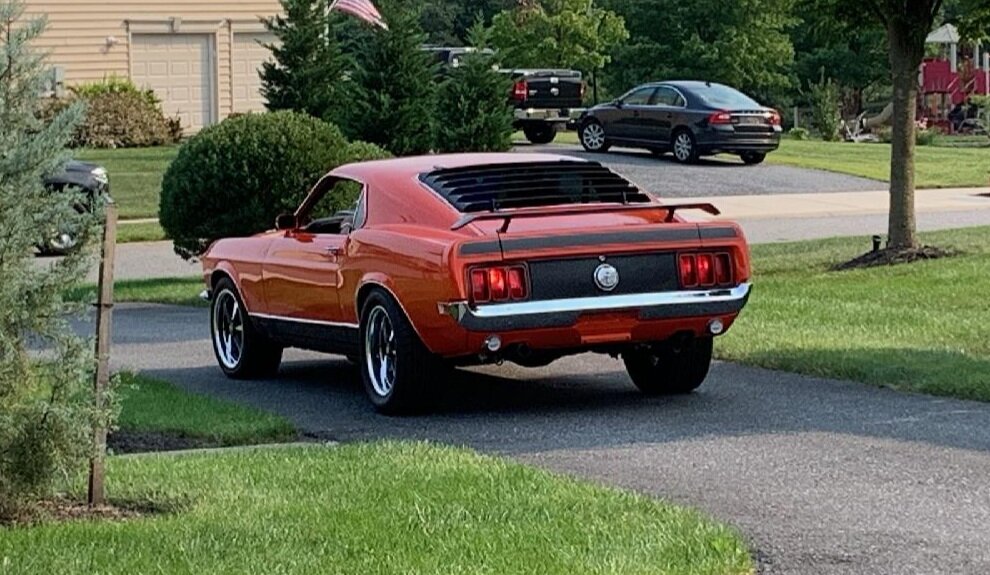
1 minute ago, pgold said:AAAwsome looking car. Comprehensive restoration to be proud of. You may need to consider crowd control when showing. I love your red and black interior.
Hey thanks man. After all the hard work, I am looking forward to getting her out in public and showing her off a little.
-
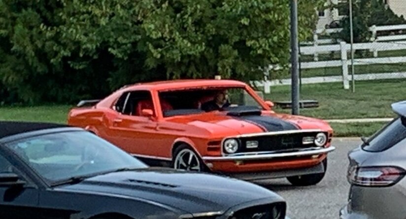
17 minutes ago, copb8 said:wow Wow WOW!!!
You're car is spectacular. I can't imagine how excited and proud you must be.
Congratulations.
Thanks!. Yes, I can't wait to get out and about, and to a few car shows and show her off.
-
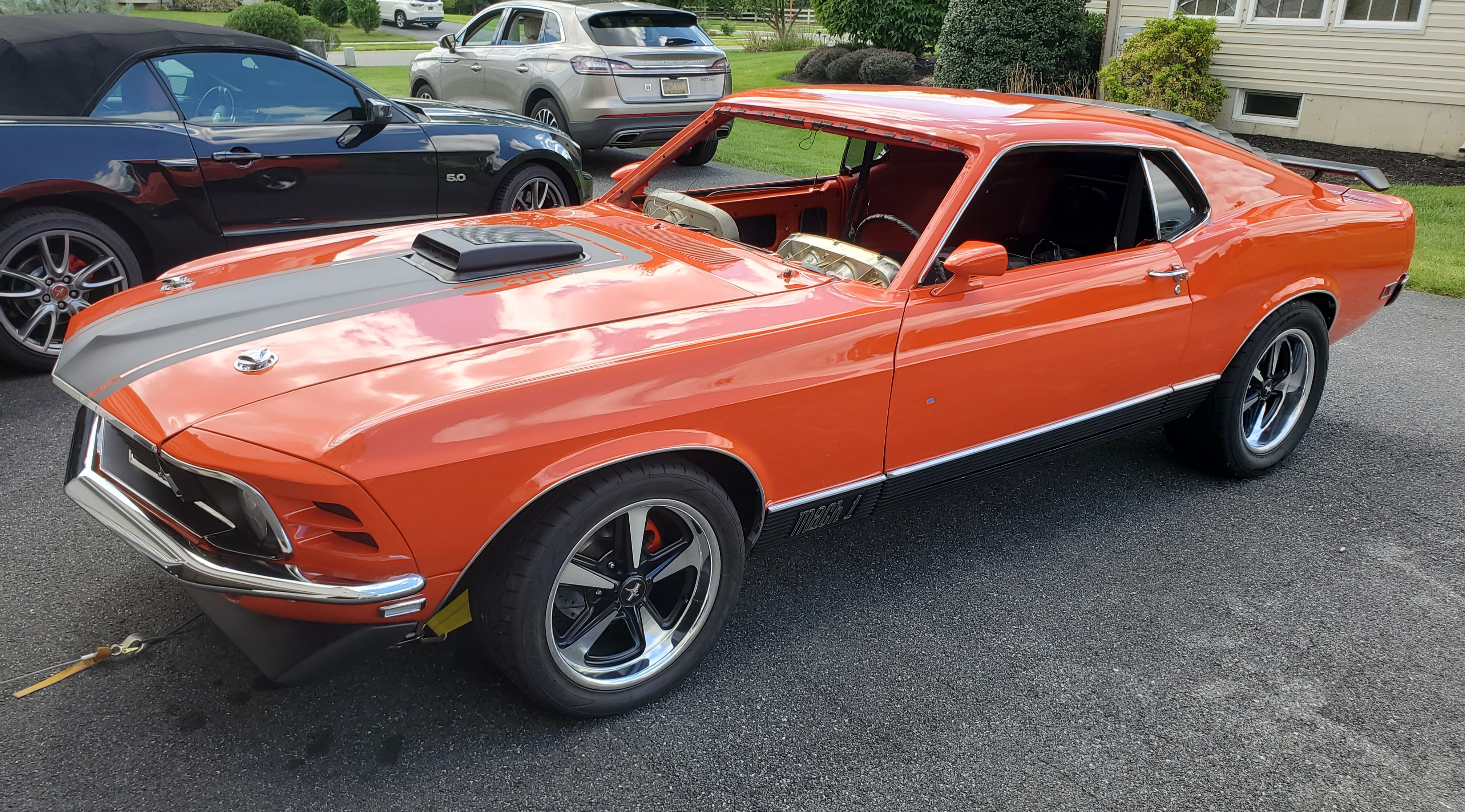
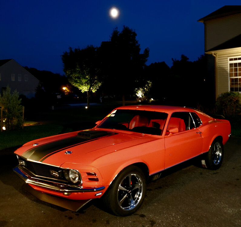
Well, took her out for a drive. First time she move3d under her own power since 1983, when the P.O parked it. My wife snapped a few pics of it as I left the drive for a quick trip around the block...Still no windshield, but nothing too strenuous. Still needs and alignment and some muffler work and a DMV inspection....
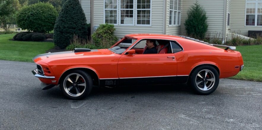
After I parked it in the driveway, I came out later to put her in the garage and saw her illuminated under the evening sky and had to snap one more picture... Just love that Calypso Coral color!
 Grabber70Mach reacted to this
 -
-
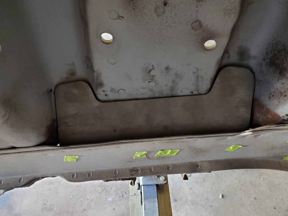
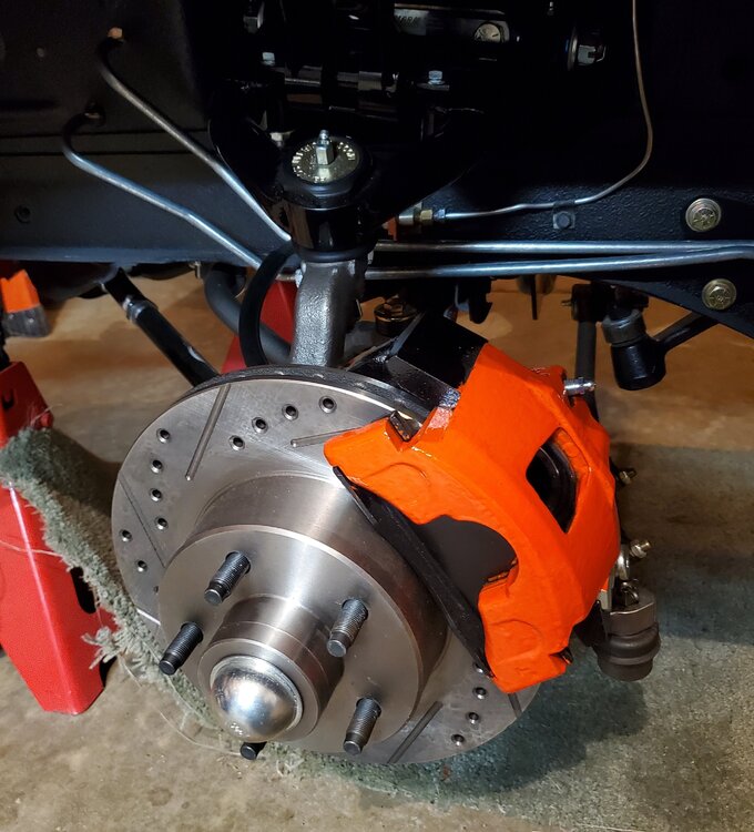
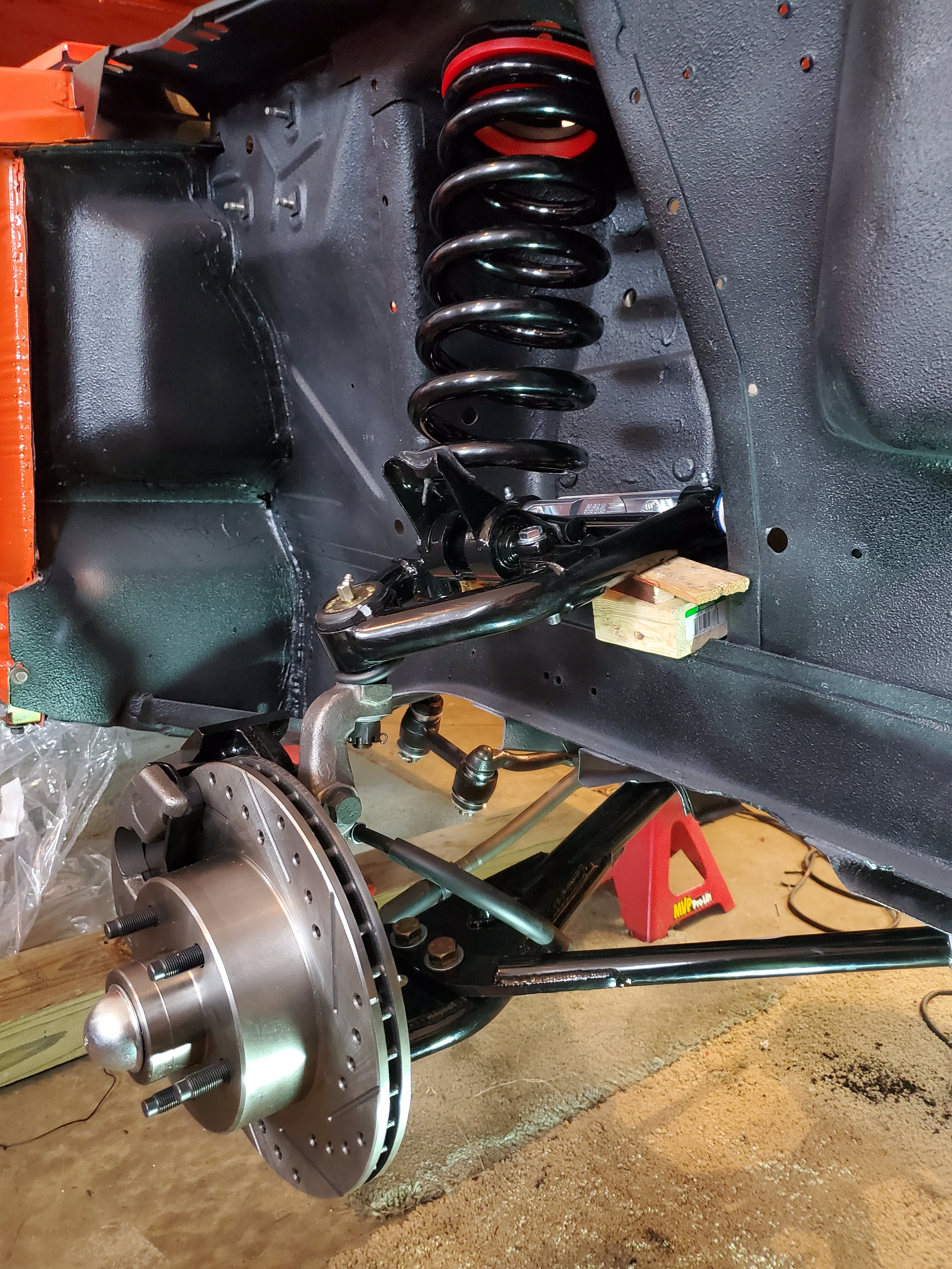
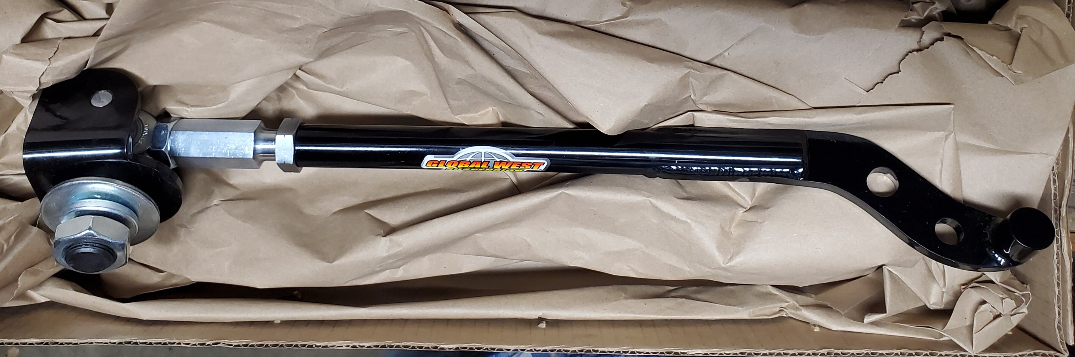
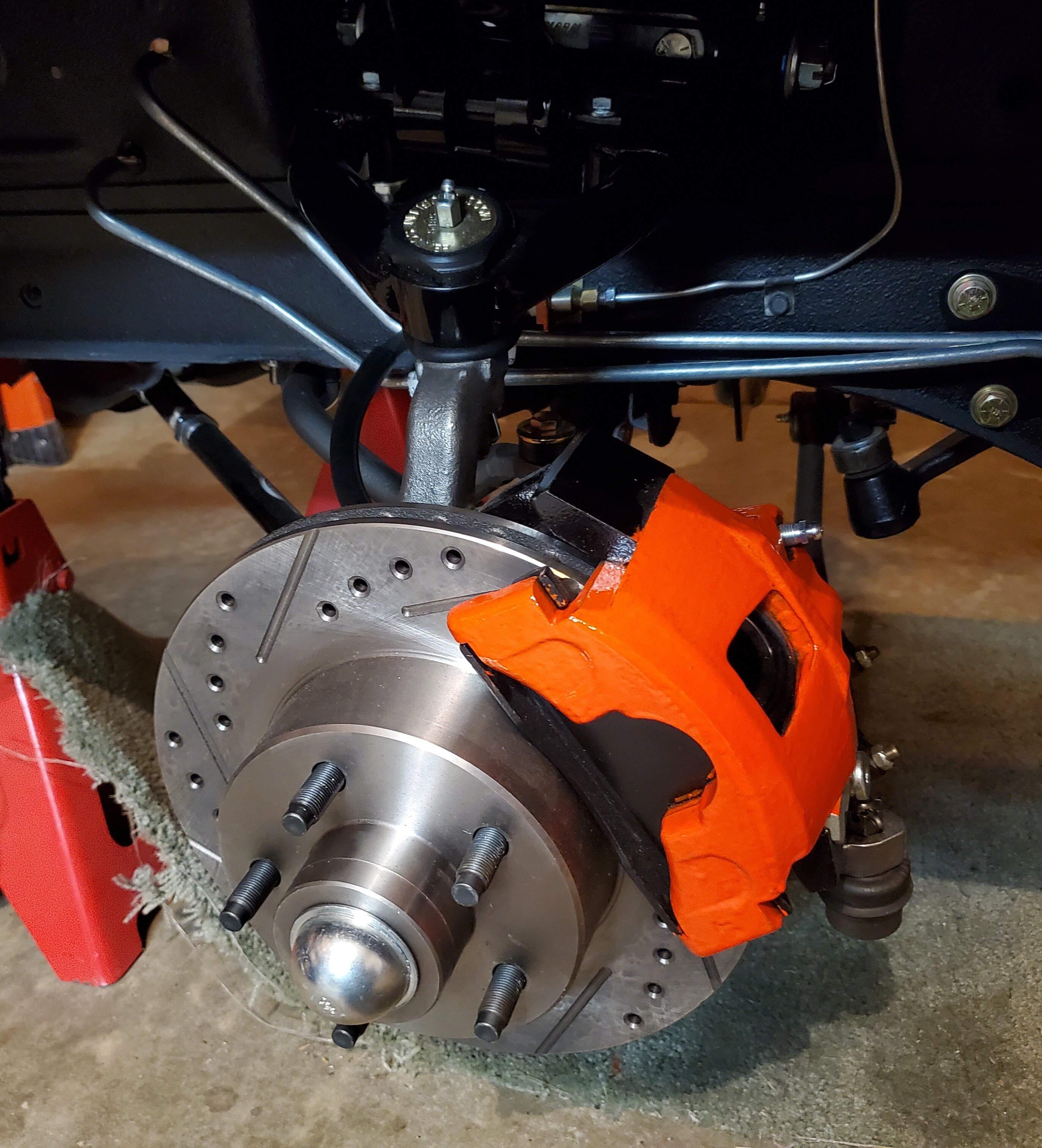
On my 70 MAch 1 I installed Global West Tubular Upper upper and lower control arms and their adjustable strut rods. Also used their Eccentric Loc-Outs. The kit provided a 1" drop steel template for drilling the lower upper control arm pivot holes. I installed Global West Coil Springs (#: s-27), which are stock height performance street with 640 pounds per inch. I welded in some of the BOSS track Mods... the Shock Tower reinforcements plates and the crossmember lower control arm eccentric anchor plates (I chose to use Global West Eccentric Loc-Outs instead). I also converted my manual steering to a CPP GM style power steering setup and swapped my front spindles and drum brakes to stronger Granada front spindles, and calipers with slotted/drilled rotors. I just finished the restoration, and have had limited opportunity to drive the car, but so far so good.
Here is the Global West Suspension product description...
1967-1973 Mustang Plus 3 Upper Control Arms # MNR-733 (Sold as a Pair)Global West has engineered an upgraded upper control arm for 1967, 1968, 1969, 1970, 1971, 1972, and 1973 Mustangs; the arm provides additional positive caster by moving the upper ball joint back towards the rear of the car.
This particular kit is used for street and handling applications. (Global West also manufactures a control arm for drag racing / street.)
The new Plus 3 Mustang arms are shipped assembled with billet cross shafts, Del-a-lum bushings and ball joints. The a-arms are black powder coated and the cross shafts are blue zinc (silver). Global West manufactures this product in its own facility here in San Bernardino CA.
Tech Information: Caster
With upgraded suspension and present tire technology, caster plays an important part for proper handling of the car. Caster does the following: provides straight line stability, has a self centering action on the front suspension, improves initial turn in during cornering and also resists pulling (right hand drift) caused by road crown.
The Alignment Adjustment and Limitation:
Caster on 1967-73 Mustangs is adjusted by moving the lower control arm forward via the strut rod. The strut rod is threaded at one end where the rubber bushings reside. By loosening and tightening the jam nuts you can pull the lower arm forward gaining more caster.
This was not an option on 1967-1973 Mustangs. The real limitation on how much caster you can get is mainly based on the rim and tire combination you are planning on running. The larger sizes limit how far you can move the lower arm forward because the tire runs into the lower portion of the front fender when the wheel is turned.
If this occurs, you will have to reduce caster, which is not the best answer. Now with Global West Plus 3 upper arms you will be able to get the caster you need!


 Mach1 Driver and bigmal reacted to this
 -
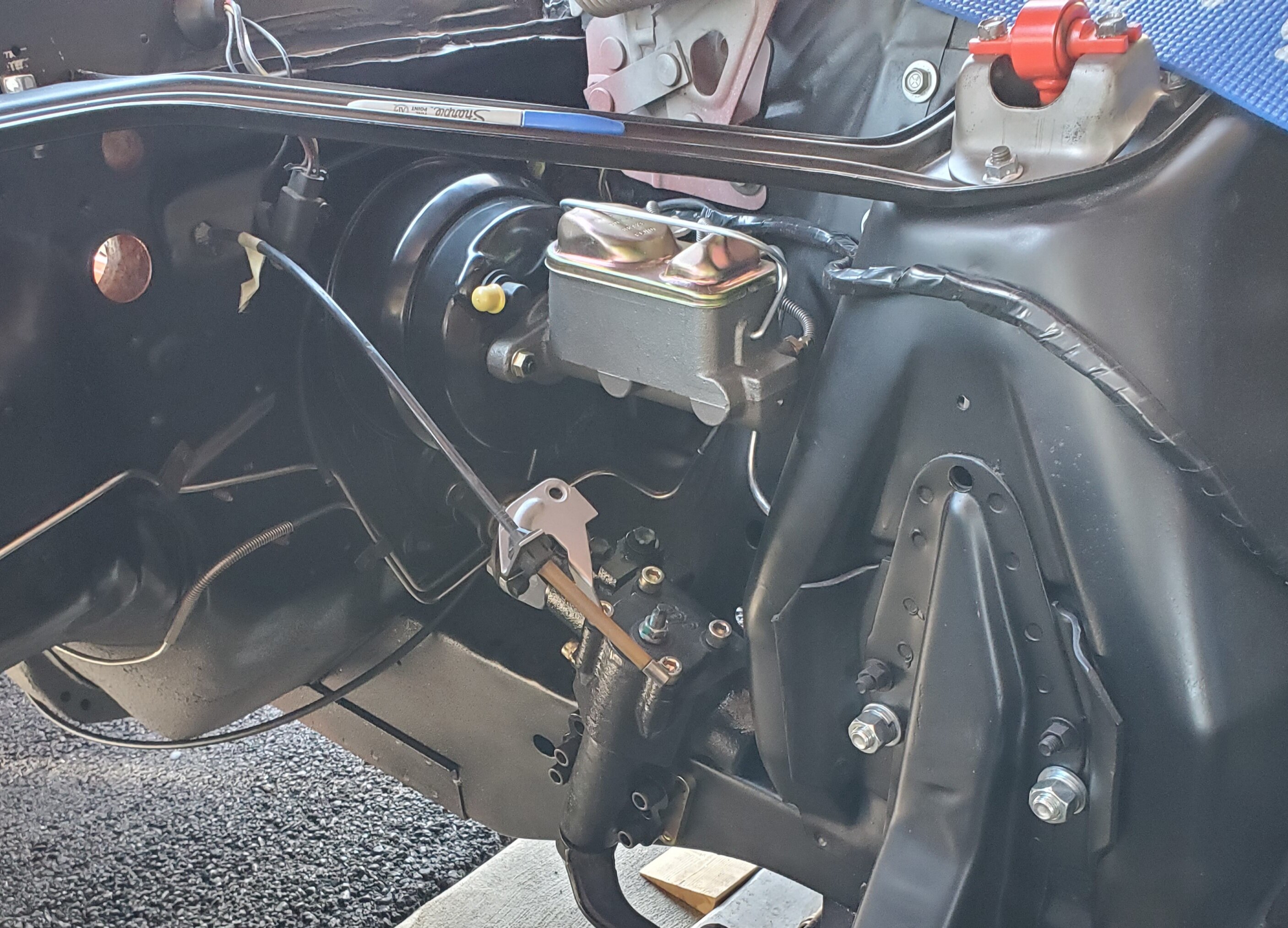
7 hours ago, rr03cobra said:hey Rich. I'm converting my drum/drum to disc/disc system from MP Brakes. My original brake lines come straight up from underneath. It looks like I may have to bend the front brake lines to connect to the valve. I don't have the original setup so I can't look at if for a reference. My question is did you buy new front brake lines or modify the old ones? Are these pictures the latest setup that you did?
Thanks.....Rich R
Hi Rich,
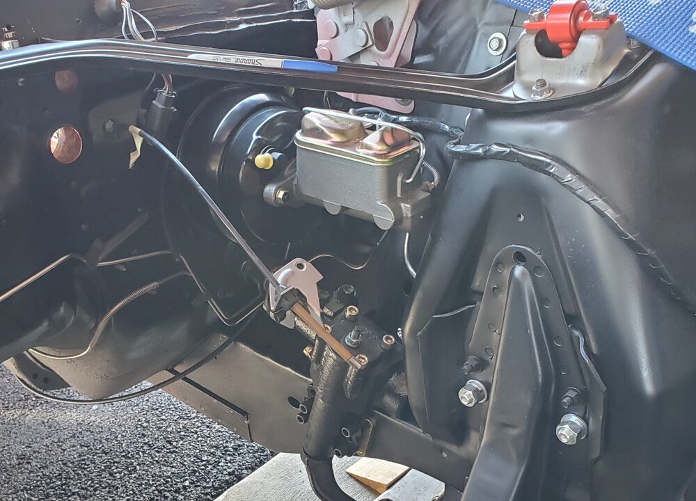
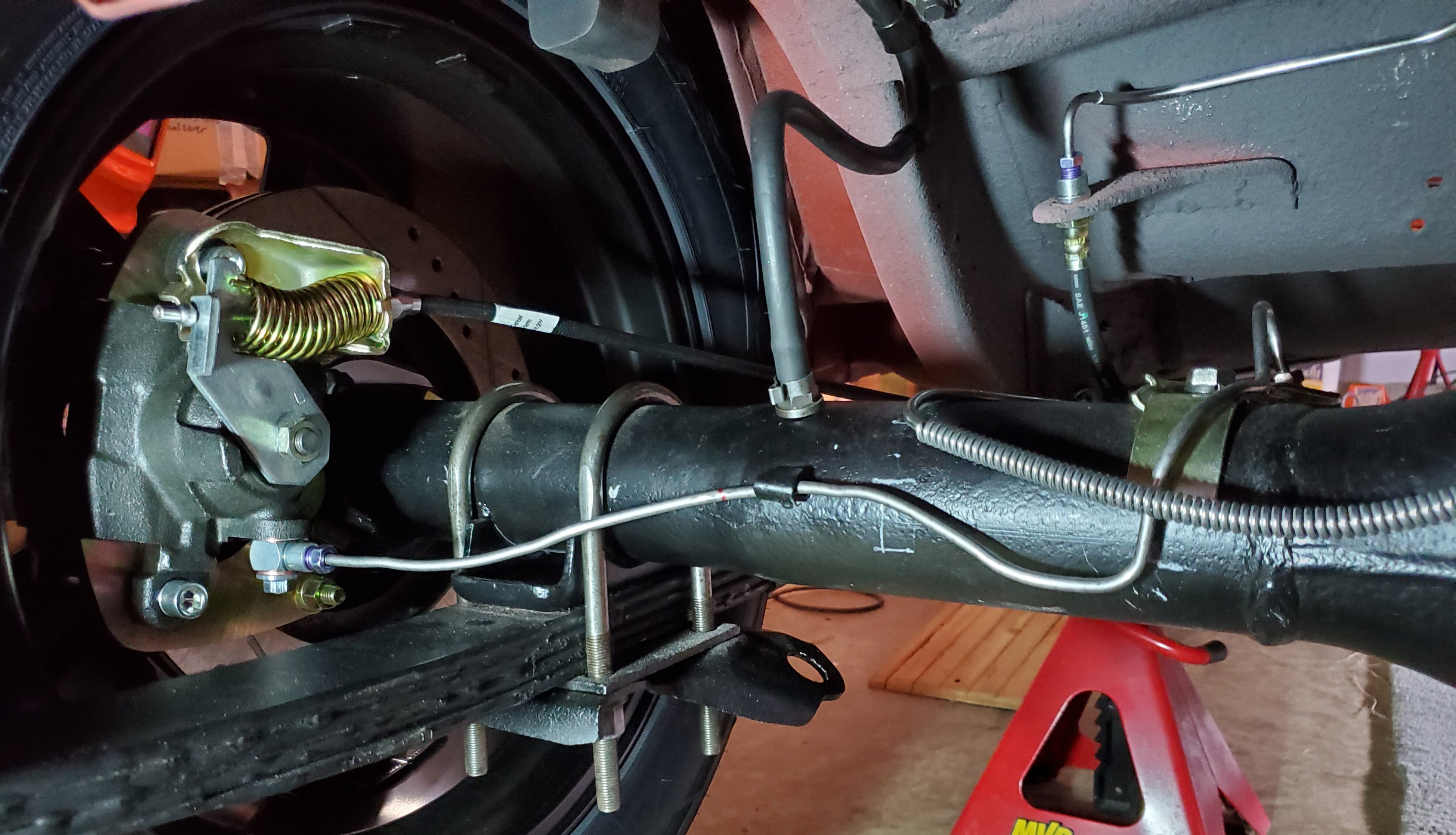
I replaced all of the brake lines. Don't use 50 year old lines with your new brake system. I bought the 1970 Mustang kit from Inline Tube. All the lines will need some modification. I prefer to use Stainless Steel. but it is much harder to work with...hard to bend, and if you need to trim them, it is impossible to flare the ends with hand tools. So I would recommend using Steel lines.
The line from the rear to the Proportioning valve will need some bending to line up, as will the two front lines. The lines from the valve to the master cylinder will need to be bent. My conversion kit cam with rubber lines to connect the two rear lines to the rear disc caliper, but I chose to go all hardline instead. The rear lines after the junction "T" on the axle will need to be trimmed and bent to line up with eh rear calipers. The critical part for me was finding the Banjo to 3/8" female inverted flare to connect the existing hardline fitting to the rear caliper.
My front Granada disc brake assembly came with the flex lines. I needed to add an adapter to connect the hardline fitting to the flex tube. I also need to install a mounting bracket to secure the hard line and flex tube to the frame.
Finding all the right fitting adapters took a lot of time a searching and some trial and error. If you have access to a hydraulic flaring tool and know someone who can help you make the tubes with the right flares and fittings, then that may be a good route to take.
Finally, you will need to make some mods to the parking brake cable ends to adapt it to the rear brake calipers. Also you will need a GM Proportioning valve Brake Warning light plug. Our Mustang have two wire plugs and the GM plug is one wire. Just twist the two wires from you Ford harness together and connect it to the GM one wire. Let me know if I can provide anymore info.

 lalojamesliz reacted to this
 -
3 hours ago, EastYorkStang said:Very cool. Ever thought of getting the dash and console wrapped with red leather ?
I like the black carpet, dash, console, and rear fold down. I think those parts in black contrast nicely against the red seats.
Thanks
stangs-R-me reacted to this -
4 hours ago, Midlife said:4 hours ago, Midlife said:Circuit breaker is not a substitute for a fusible link, as with a massive short, it will simply switch on and off repeatedly. I believe (please don't quote me) that the fusible link needs to be 4 AWG sizes larger than the main power line.
Randy,
I was thinking of a Manual Reset Low Profile ATC Circuit Breaker. Essentially an ATC type fuse that can be reset. An auto reset breaker would be pointless.Thanks
-
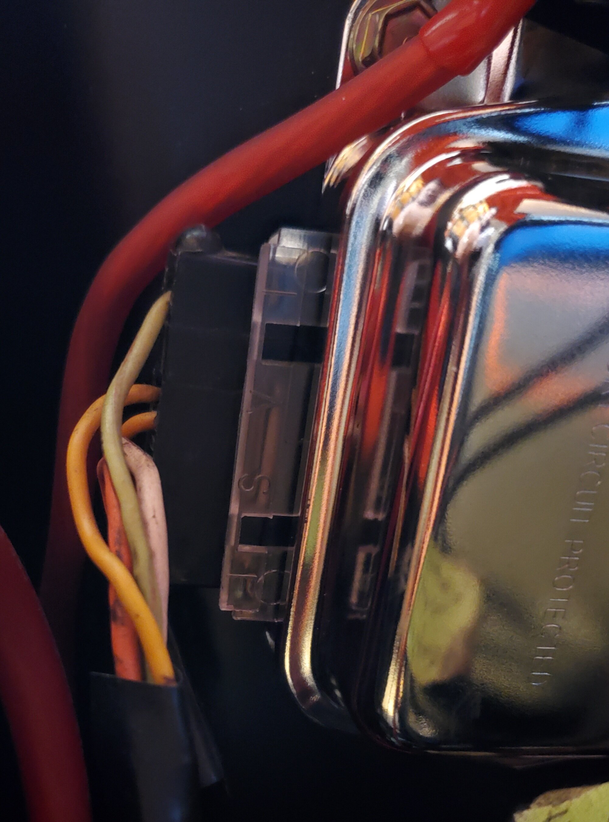
11 hours ago, Midlife said:That fusible link is not a factory correct 1970, as in my experience (close to 125 1970 refurbishments), I have never seen the green flag on any of the power leads: just a black wire, perhaps with some writing on it. The flags first appear in 1971.
There is another useful thing about fusible links that I failed to mention above: if the car is sitting in a garage, not on, and somehow a massive short is initiated, the fusible link will prevent current flowing from the battery and thus the rest of the wiring is protected to a certain degree. It will definitely stop an electrically induced fire when the car is off or the key is in ACC or RUN but with the engine not running. Perhaps that was the reason it was implemented.
As far as wire gauges go, what Ford used and documented is somewhat inconsistent with what is typically found today in wire sizes. I suspect there was either a change in AWG specifications or Ford used a slightly different gauging system that what is currently used today. When I buy 18 gauge wiring, it is somewhat thicker than the Ford product when the insulation is removed. The fusible link does appear to be about 2-4 AWG sizes less than the main power line.
Randy,
Yes, I am not sure what year Mustang the Fusible link wire is from. I know its not from my 70 Mustang.
Any reason not to use a manual reset breaker instead of a Fusible link? Does your point about protection from a massive short while the car is parked work with a Breaker as well? I would think so. How many sizes smaller is best? or example use a 14AWG fusible link wire with a 10 AWG wire or 12AWG fusible link wire with a 10 AWG?
Thanks as always for your help.
Rich
-
13 hours ago, Mach1 Driver said:Tuff Stuff says that the alternator has a Ford style front case, a GM style rear case with heavy duty copper coils, spike resistant diodes, and an external solid state voltage regulator. From experience you know that the regulator can't be connected as the OEM regulator was. This is a combination of parts that doesn't operate the way the old system did, and you will never know what goes on inside their regulator.
So, here are my recommendations:
1. Remove or disconnect and tape wires 904, 152, and 38. You will not have an alternator warning light.
2. Connect a 14ga fuse link between wire 37 and the terminal block. Do not bundle the fuse link into a harness with other wires- let it hang loose so if it melts it doesn't destroy other wires or harnesses. Its a fuse so let it do its job. If you need a source for this I can find it.
3. Put a mega fuse between the alternator battery terminal and the terminal block.
That's correct the alternator is considered and hybrid front Ford and rear GM to accommodate the larger internals needed for the 140amp. I understand and will do 1, 2, and 3. Thanks so much!
Question for you and Randy, Any reason not to use a manual reset breaker instead of a Fusible link?
-
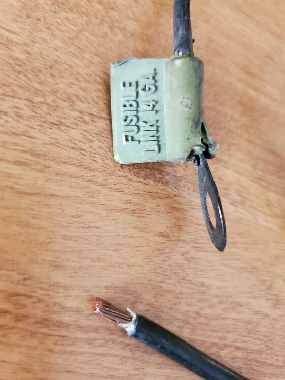
6 hours ago, Mach1 Driver said:I have read that its just regular copper wire- but smaller, so it should blow first in a high amp condition. By chance do you know the gauge sizes for 38 and 38A on the 1970?
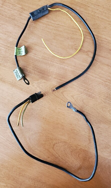
Here is a picture of a portion of the alternator wire harness I removed when converting to the 140amp Tuff Stuff Alternator. The 1970 wiring diagram says Black wire 38 and black/yellow accessory 37 wire are 10 Gauge. Yellow 21 Ignition switch Accessory is 12 gauge. Although missing from my harness the 38A fusible link pigtail to the battery side of the solenoid branched at the connection of wires 38 and 37.
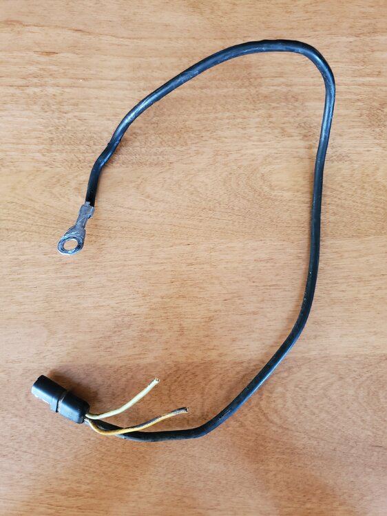
I cannot confirm what year the wire below is from, but here is a picture of the end of 38 and Fusible Link 38A. You can see the fusible link on wire 38A which is the lead to the battery side of the solenoid. It says 14 G.A and Black wire 38 is 10 gauge to the 2 pin plug is missing on the end. This wire is setup differently with the yellow wire 152 junction in the middle rather than at the plug as it is on my 1970 wire.
-
On 9/8/2021 at 4:09 PM, Mike65 said:WOW Rick your mustang looks great!.
Thanks!
-
12 minutes ago, Mach1 Driver said:Rich, you have already stated "The Alternator is running and charging great...no operational issue there. My issue is the Alternator light stays on and will not turn off. I called Tuff Stuff Tech and they told me I did not need to connect the I (ignition) wire (#904 Green/Red Stripe) from the regulator".
They have told you to disconnect wire 904. Their regulator is electronic and doesn't function the way the electro-mechanical one does. I would ask them if anything needs to be connected to A, but according their document it doesn't.
If you want to know how the OEM system operates, then take the time to read my paper- it is too lengthy to be discussed here. Besides, you're not using it anymore. The Tuff Stuff system is "electronic", while the OEM system is many decades older and "electro-mechanical". A tech on the phone is unlikely to have knowledge of the internal workings of their circuit. Its an apples and oranges comparison. They don't need the same inputs and outputs, and they won't publish details of the internal workings. Welcome to the wonderful world of generic aftermarket parts.
I look forward reading your paper thoroughly. I will call them and get clarity on term A wire as well.
Anyway, I thank you very much for taking the time to answer my questions in an effort to sort this out.
Regards,
Rich
-
5 minutes ago, Mach1 Driver said:The black wire you are referring to is 38?
Power goes from battery+, to the terminal block, to 38, to 37, to the ignition switch B, to C in ON and Start, then back via 904 red/green to the battery+ again? That sounds like it is going nowhere. To alleviate any problems I would just remove 904, since it doesn't do anything anymore. As I mentioned earlier, I don't believe your wire diagram is 100% correct. I have found a number of problems on many wire diagrams- even my own Ford authorized drawing is incorrect in several places.
Yes. The black wire #38 10 AWG which originally connected to the stock Alternator and thru a 2 pin plug to the Battery side of the regulator and also to the #37 Black/Yellow Accessory wire, now goes directly from the terminal block to the #37 Black/Yellow Accessory wire. The new 6 AWG wire goes from the T. S. Alternator directly to the terminal block.
The path according to Ford #904 red/green wire goes from the I term on the regulator to the other pin in the 2 pin plug along with Black wire #38 then to the gauge cluster plug where it splits and one wire goes to the Alt warning lamp and the other goes to the large pin on the ignition switch plug, where it is joined with The Black/Green #297 wire. I have changed nothing with wire #904, and other than removing #38 wire from the battery side of the Solenoid and relocating the 10 AWG #38 wire from the original Ford alternator to the terminal block, where it now meets up with the new 6 AWG wire from the T. S. alternator.
-
1 minute ago, Mach1 Driver said:Did Tuff Stuff say its ok to connect to regulator A and I? Nothing is shown on the instructions that I can see. Most people would put a mega fuse on the 6ga from the alternator to terminal block. Wire 37 is power to most of the car, so if there is a fuse link I would expect it between 37 and 38, or upstream from 38 to the terminal block.
When I talked to the tech at Tuff Stuff, I told them that I was using the stock harness and regulator plug. My focus was on terminal "I" and the warning light on. The Tech told me to disconnect "I", which bring us full circle and my reason for this post. I am uncomfortable with having the I (ignition) wire (#904 Green/Red Stripe) from the regulator. disconnected. Ford put it there for a reason. I would prefer to have the Warning Light working as it was intended, but I would prefer to get confirmation that there is no harm with disconnecting it.
I did ask the Tech about fusing the wire to the Alternator. He said and I quote "Don't waste your money fusing it"
-
3 hours ago, Mach1 Driver said:Rick, if you want to understand how the OE system works, go to "How tos" on this forum, and read my paper "How Alternators Work". It will explain both types of systems used on our cars- those with and without the alternator light. Your new regulator doesn't work like the old one and the warning light is just disconnected in your case. Your voltmeter will tell you what is happening, and is much better than the ammeter used on my car. Unfortunately manufacturers try to make this stuff so generic, that their instructions are next to useless.
What did you do in step 7? The reason I ask is because you replaced about a 38A alternator for a 140A, and one of the things they don't seem to tell you is that it could smoke Black wires 38 and 38A, if its cranked up all the way during charging. The wire gauge size is just inadequate, but they are short wires so that may save them- but I'll bet they get hot. Most people that install these humongous alternators attach a battery cable to the alternator positive, that goes to a mega fuse (around 200A) and that attaches to the left solenoid terminal.
Hopefully Midlife can chime in here, because I don't have a 70 wire diagram and I know that the 70s were the first year to have a fusible links...I'm guessing from the solenoid left terminal to wire 37 and possibly some other wires?? It isn't shown on your diagram so we need that bit of the puzzle before making a thorough recommendation.
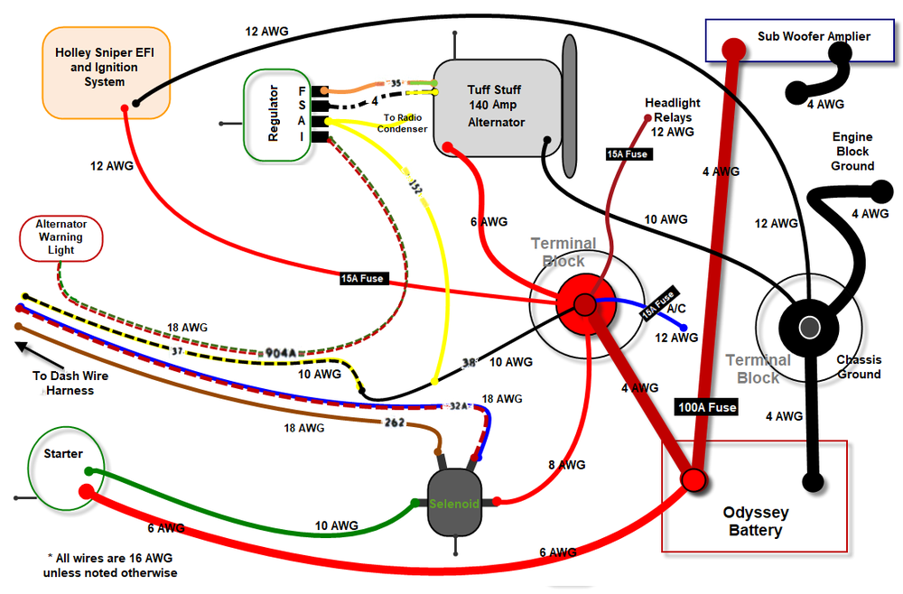
Your point about the inadequate wire size is an excellent one, and was something I realized from the beginning, so with the new Alternator I ran a 6 AWG wire (which is what Tuff Stuff recommended) to a Terminal Block I installed. I have a 4 AWG wire from the terminal Block to the battery post. The factory black wire and the 904 Green/Red Stripe in the factory harness two pin plug now go to the battery post as well. The rest of the factory harness to the regulator is the same as it was. I also have a 10 AWG wire from the Alternator case to Chassis/Block ground. I question Tuff Stuff as to why the ground does not need to be 6 AWG like the positive wire, and they said the Alternator case is also grounded thru the mounting brackets to the block. Finally my Starter and Sub amp come directly off the battery terminal and are both 4 AWG. The Stater has a secondary 8 AWG wire from the Solenoid and the Sednoid has a 6 AWG wire to the battery post.
Step #7 I ran 6 AWG wire from the Alternator to a Terminal Block and a 4 AWG wire from the terminal block to the battery post.
All that said, I think I have made sure that all my electrical wire size is sufficient. I just spent the past hour drawing up an electrical diagram. I am no artist but I think I have clearly depicted what I have with the wire sizes.
-
Hi Randy and other Ford wiring Experts,
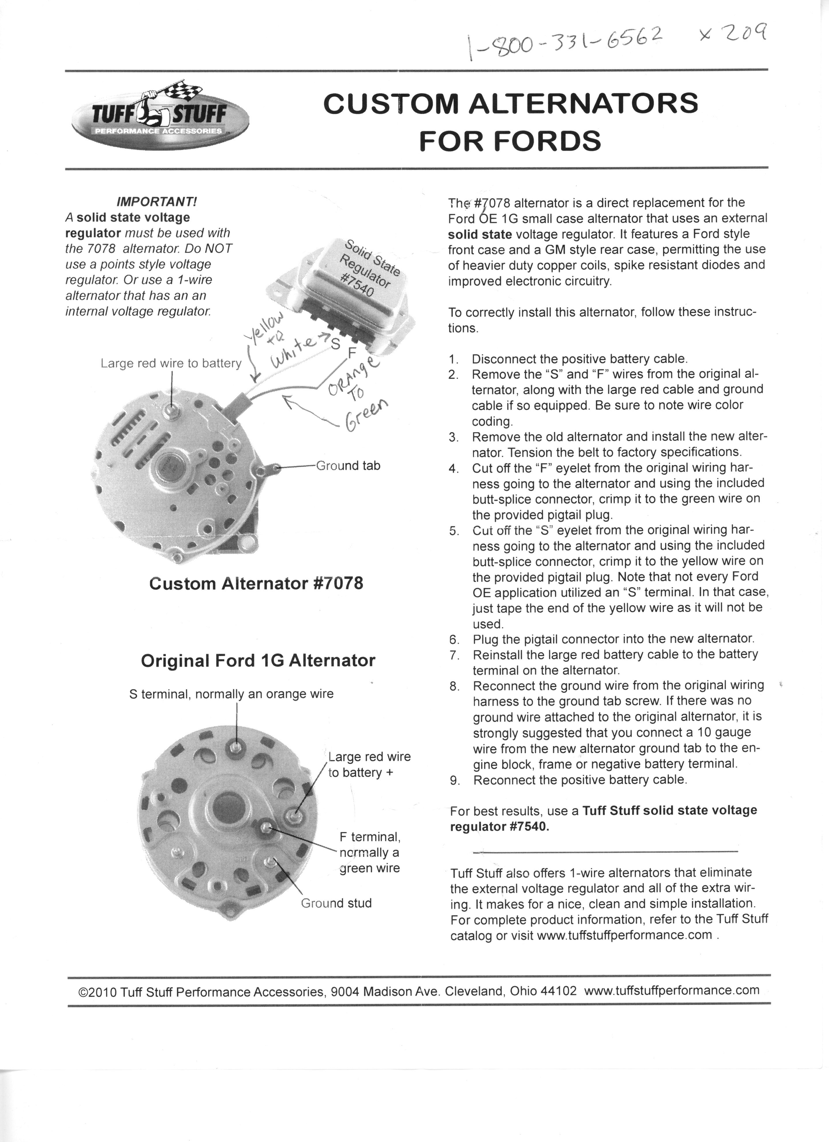
I installed a Tuff Stuff 140 amp Ford 1G Hybrid Alternator and a Tuff Stuff electronic Regulator in my 70 Mach 1 with a factory tachometer. I modified the stock wire harness according to the Tuff Stuff instructions (see below). I am using the factory wire harness from the regulator.
Regulator Terminals
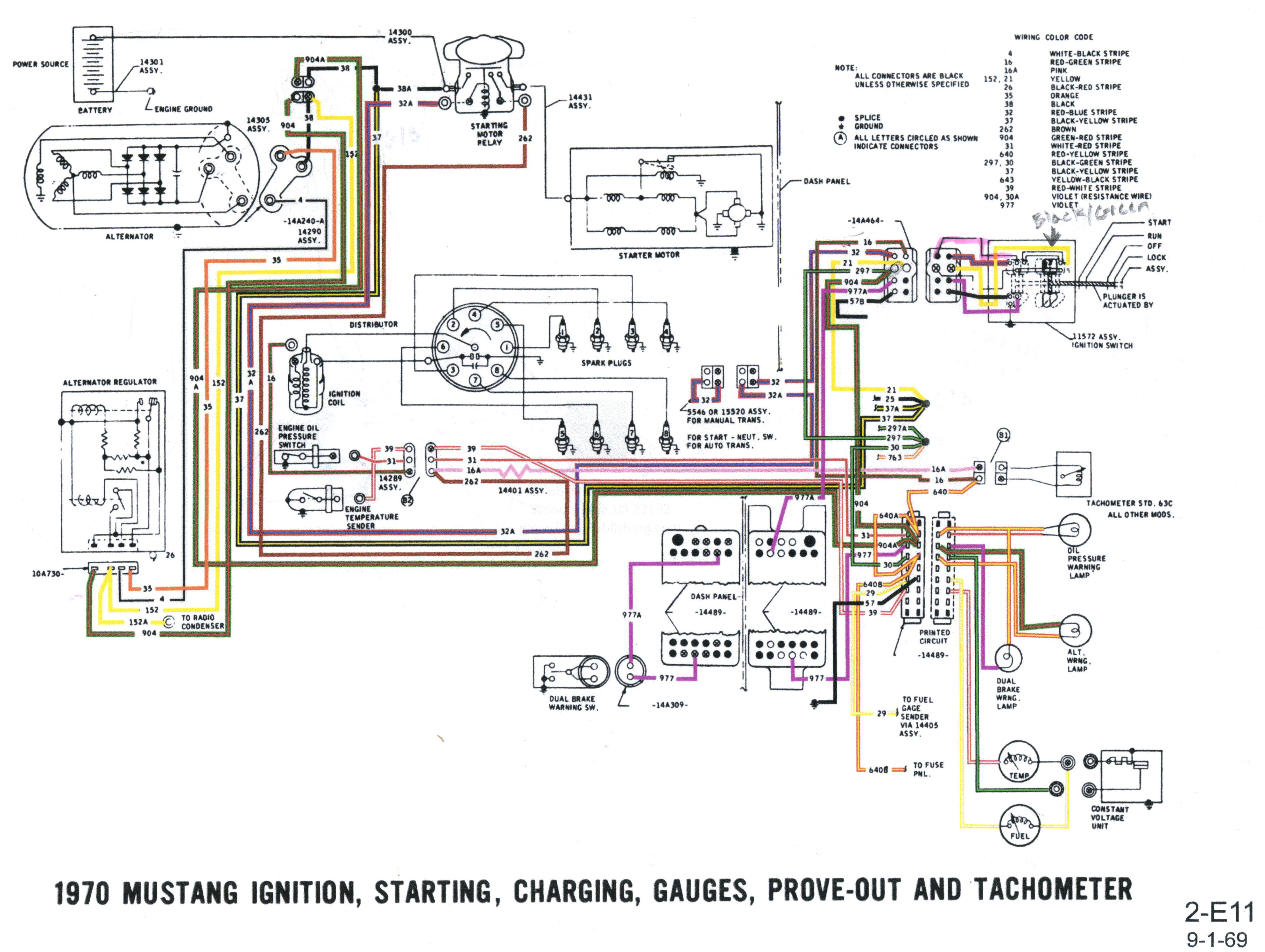
(I = Ignition (#904 Green/Red Stripe) to Alternator Warning Lamp and Ignition Switch (where #904 also connects to #297 Black/Green Stripe) as shown in the Ford Charging/Prove-out wiring diagram.
A = Battery (#152 Yellow) to Tuff Stuff Alternator Red wire
S = Stator (#4 White/Black Stripe) to Tuff Stuff Alternator Yellow wire
F = Field (#35 Orange) to Tuff Stuff Alternator Green wire
The Alternator is running and charging great...no operational issue there. My issue is the Alternator light stays on and will not turn off. I called Tuff Stuff Tech and they told me I did not need to connect the I (ignition) wire (#904 Green/Red Stripe) from the regulator.
I disconnected the I (ignition) wire (#904 Green/Red Stripe) and started the car everything appears to be working normally with this wire disconnected and the Alternator Warning Lamp is off.
I am uncomfortable with having the I (ignition) wire (#904 Green/Red Stripe) from the regulator. disconnected as Ford put it there for a reason. Since other wires (#297 connects to the Ignition Switch and #640 connects to the other terminal on the Alternator warning lamp)) in the Ford harness are connected. Finally the Warning Lamp is now disabled. Fortunately I have a Volt Meter gauge as well, so I can live without the warning light.
Does anyone who understand how the Warning Lamp work as Ford intended it to see a problem with disconnecting (I = Ignition (#904 Green/Red Stripe) from the Regulator?
For my own edification, how does the Regulator and Alternator Warning Lamp circuit actually work to cause the Lamp to light?
Thanks,
Rich


-
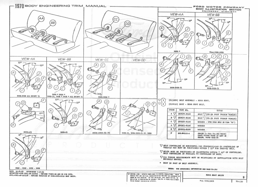
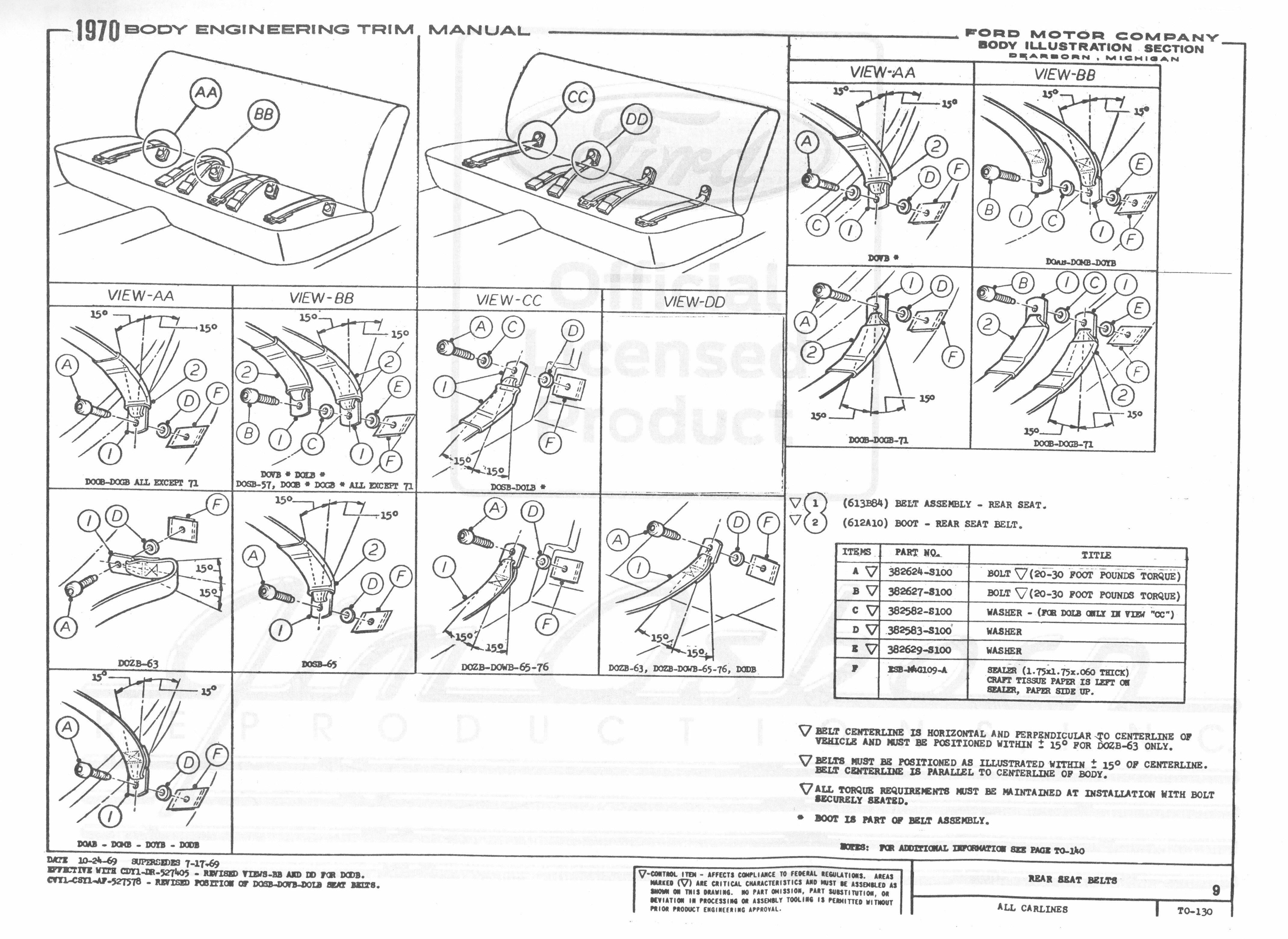
2 hours ago, Rcodenewf said:Thanks Rich: Not sure what the difference would be between B on the top left and B on the top right? I had seen this diagram on my microfiche but again wasn't sure which diagram would apply. The B on the left has a washer above and below the belt whereas the far right b diagram has one small washer under the buckle. Where the confusion lies is that i have 7 of those small washers..lol...and i'm a bit of a collector so i could have thrown extras in the box with the ones i took off...Or...i'm missing one. I think i had extras. The rear ones aren't required to pivot and therefore should only...i think ..have one washer under the buckle as the bolt does not have a shoulder.
Thanks for the response!
Regards..John
Hi John,
The diagram is confusing. This diagram applies to all ford for multiple years. This is the full version and may clear up the confusion. It show option for doubling up the belt for center seats (cars with three seats across the back. Also apparently some cars the seatbelt anchor is position up and others are down.
-
On 7/21/2021 at 2:10 AM, smh00n said:I have a Sniper but with MSD Pro-billet. Wiring that one component caused me more hassle than the entire carb/tank/wiring process.
Holley really need a better instruction writer, as I found their instructions wrong too. Sniper instructions said wire this way, MSD said wire that way. Can't remember the answer now but I'm sure the MSD instructions were right and Holley wrong.
You'll like the Sniper, just works when wired right. Cold starts are like a new car, no hesitation at all. Heck, all starts are like a new car :)
You are spot on. Now that everything is installed correctly. It starts right up every time.
-
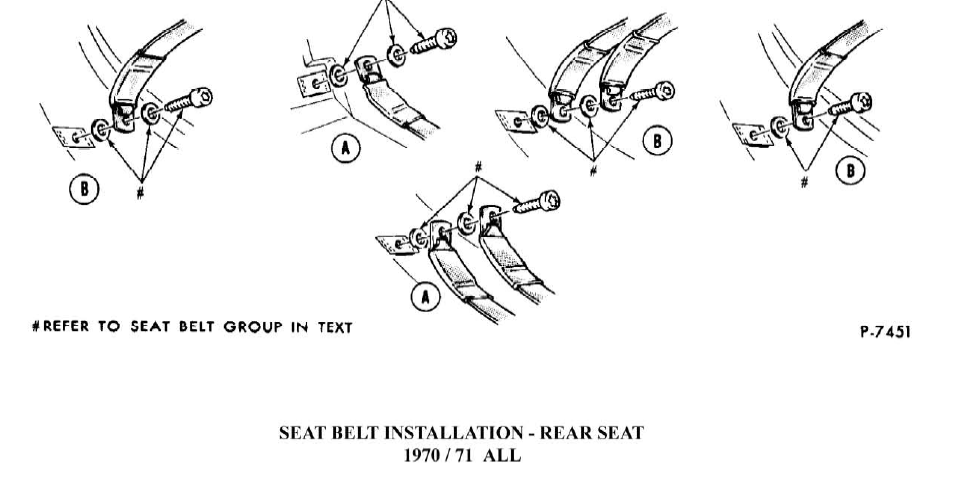
7 hours ago, Rcodenewf said:The rear seat belt bolts are shorter than the front bolts and have the same thick washer. The front ones have the rubber washer whereas the rear has a serrated reddish washer. Does this washer go under the big bolt and on top of the big washer or underneath the big washer.
The rear short bolts ive noticed has an "A" stamped on the head whereas the fronts are stamped "B".
Thanks...John
-
1 hour ago, EastYorkStang said:How did you wire in the intank pump ?
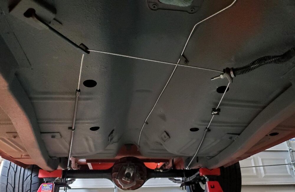
I ran 12 gauge (blue) wire, 12v from the battery thru the left hand rocker channel and out the quarter panel drop down to the four pin plug supplied with the Holley pump. The 12v supply from the battery is controlled by a relay mounted in the engine compartment. The Holly sniper will trigger (via the pink wire) the relay with the key in the ignition run and start positions. The Holley EFI system, Hyperspark ignition, and fuel pump requires power to be on when the key is in the run position to prime the pump and it must maintain continuous power when the key is turned to start, so it is important to connect your ignition start wire to a relay and connect the Holley Sniper pink wire to the relay pin 87, 12v to pin 30, and your ignition start wire spliced to pin 86, and ground to pin 85. In addition, I ran a 12 gauge wire ground from the engine compartment to the four pin Holley pump supplied plug, but you can ground a 12 gauged wire to the chassis near the pump/tank. The purple 16 gauge wire from the pump connects to the factory sender (yellow) wire to the Fuel Gauge in the dash. The fourth wire is a 16 gauge Black/White Stripe wire from the pump harness is for the sending unit ground. This can be grounded near the tank as well. You can see the pump wire harness and plug in the pictures I uploaded in the previous post.
I hope that helps...
-


Shelby Drop questions.......again
in 1969-70 Technical Forum
Posted · Report reply
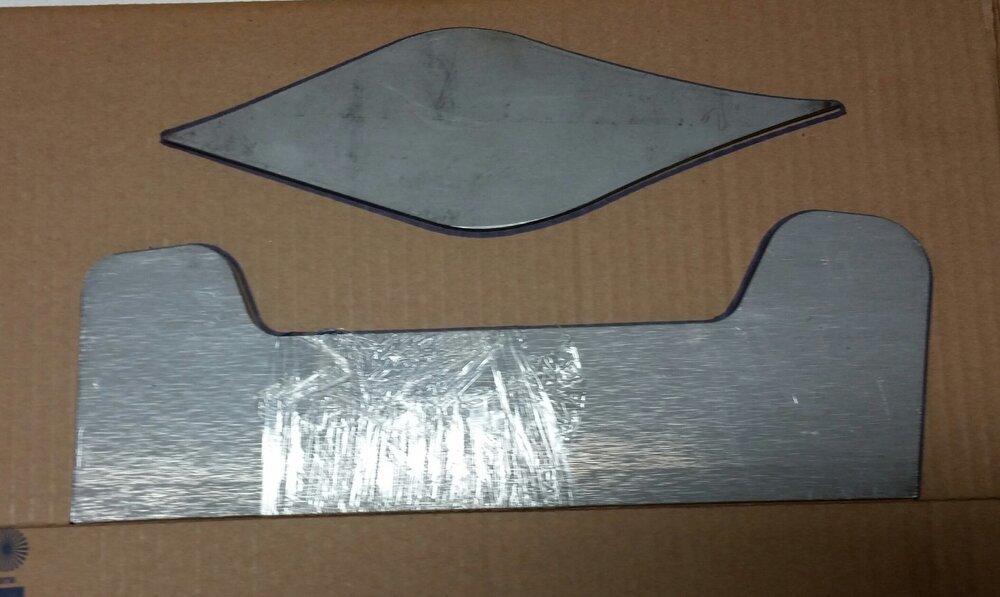
Vicfreg,
Very nice setup. I thought about going with a coil over, but in the end chose not to. Looking at yours I wonder if I made the right decision.