


Mach1 Driver
-
Content Count
2,138 -
Joined
-
Last visited
-
Days Won
86
Posts posted by Mach1 Driver
-
-
If the above options aren't available, the next best is National Parts Depot- ask for their best.
-
This will be an unpopular opinion- they raced these cars with front discs and rear drums, and the stock brakes were good enough for that. Friction materials have improved in the 50+ years. For the street, barnett468 recommends EBC green pads and shoes, Zray uses EBC Redstuff 3000 Series Sport Brake Pads, and says that the popular Porterfield pads are inconsistent from batch to batch.
The advantage of going stock is that you don't have to guess how to set it up as its all in the Ford shop manual, the parts are readily available and the part numbers are known. Why reinvent the wheel when something works? Yes you can get aftermarket brakes with gigantic pistons and air cooled slotted rotors, but chances are you're going to be messing around with the system to get it right, and you won't be driving it. In my opinion, unless you're married to Shirley Muldowney, the stock brakes will be fine. Just my 2 cents.
69RavenConv and JayEstes reacted to this -
It would be good to get the opinion of someone like Ridge Runner, but I don't think there is any need to pull the towers closer together. When you put the weight of the engine and trans in there, the bottom will be held in place by Zray's cross member but the top of the towers will lean in. If they come in too far you can always jack them out to put the export brace on.
-
As most everyone has mentioned, the under hood stuff is most likely to be degraded. If you intend using Alloy Metal Products, then call NPD and see what harnesses you would need under the hood for your model and engine, then decide which you want to do, and the order to do them. Since they plug into one another, you could do them one at a time.
For my Mach with a 351w there is; Wire assembly engine gauge feed, alternator feed, wiper motor repair harness, engine ground, wire & plug headlight extension, wire loom firewall to headlight (this is the main under hood harness), wiring harness turn indicator (for the hood scoop signals). I believe there are four others, but they are inside the cabin or trunk.
-
Midlife (Randy) will tell you that the under hood harness has taken a beating from heat and weather and he won't refurbish that, but any of the others he will freshen-up. No one knows these harnesses better than Randy. There is a full car schematic for a 69, and wire diagram, how to fix the instrument panel, and how the alternator works in the "How to's" section, if you are so inclined.
-
There are two schools of thought on wiring
1) Use stock OEM type harnesses from a company like Alloy Metal Products that are available from a vendor like National Parts Depot. This will have a standard fuse panel and exactly match the Ford authorized wire diagrams. The advantage here is that anyone who has a standard wire diagram can help you, or fix the car.
2) Use an aftermarket harness like available from Painless, which will use the new style fuses and incorporate some relays (neither of which is available in option 1). The disadvantage is that you can only get help from that company or someone else that has their product and has their wire diagram.
Personally I will stick with the OEM harnesses and add to them as needed- but I will make a wire diagram showing the additions for the next guy that ends up with the car (and so I remember what I did).
You will never learn if you don't try. It isn't rocket science, but it isn't for everyone.
stangs-R-me and KMD88 reacted to this -
-
You are probably going to get it balanced, so try asking your local machine shop where they get their rotating assemblies
-
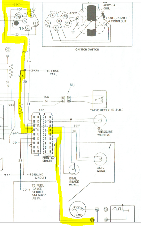
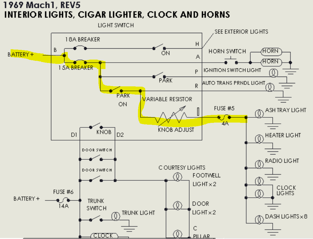
This is from the wire diagram, page 2-E7. This diagram can be found in the "How tos" section.
FYI, the "blind circuit" where it goes into the plug is just a short section of wire that is put in the terminal with the resistor wire to make a good crimp on the terminal. The resistor wire's gauge is too small to be crimped properly without it. That is a complicated wire assembly that goes to six places, as 297 connects to 904 (another resistor wire) at ignition switch A terminal. Notice where 297A goes to the fuse panel? This could shorten your search- this goes to fuse 1, which is flashers, radio and backup lights. If any of those work then you have power as far as the splice. Also, wire 30 powers the alternator warning light- does it light when the key is turned to ON- not started?
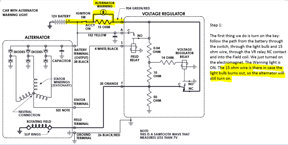
This is from "How Alternators Work" also in the "How tos" section
-
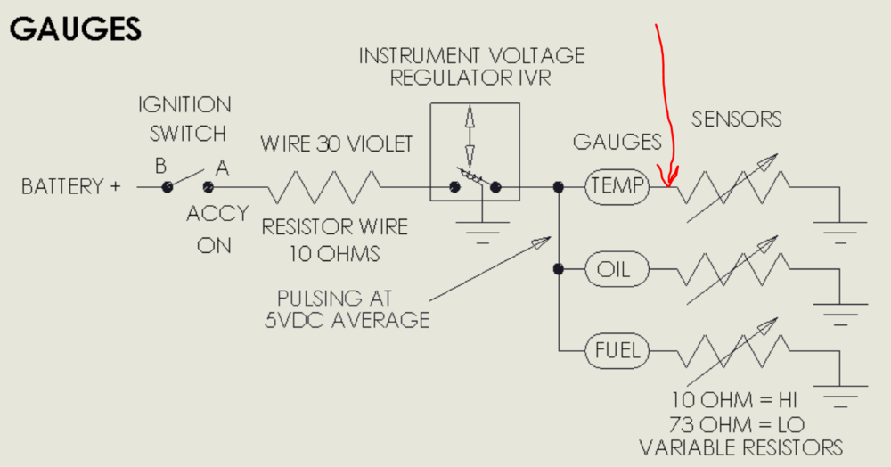
AbelG said: "I also checked for power at the violet wire at the cluster connector key in on position nothing?"
That is why the gauges don't work, there is no power to the IVR. You have a problem somewhere from ignition switch A to wire 297 bk/gr, to wire 30 violet , which goes to plug 13, and then to the IVR.
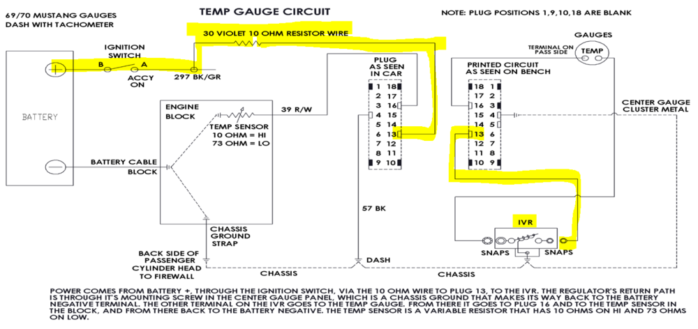
The fault may be where wire 30 violet connects to 297 bk/gr. The splice is machine crimped and I don't believe the resistor wire can be soldered- well maybe silver soldered, but not using electrical solder- it just won't stick to the wire. Find the fault and if see if 297, 30 and the other wires in this assembly need to be replaced. Also see the post below. If you need the wire assembly talk to Midlife, and hopefully Randy can help you out: http://midlifeharness.com/
-
I suggest you read 69-70 instrument gauge cluster 5.docx, in particular these pages: pg 3 gauge posts shorting to housing, pg 4 IVR, pg 6 gauges, pg 7 chassis ground, pg 18 chassis ground, pg 19 temp gauge, pg 20 fuel gauge, pg 21 oil light, pgs 22-23 "everything else".
The 4 amp fuse see page 2 of the schematic, power for the fuse comes from the light switch:

-
Hello there, you've come to the right place. As jmlay mentioned, there are several posts that would help. Go to "How to's" and look at "Fixing the Instrument Panel, "A Real Schematic", and "1969 Mustang Wire Diagram".
You've mentioned doing a 9v battery test. Actually it only takes 3v (two D batteries in series) to get the needles to sweep, but it probably did no harm. It sounds like the fault is between the gauges and the senders. So it could be the flex circuit on the back of the instrument panel, the connector to the flex, or the wires. The wire diagram shows both tach and non-tach car wiring- just find the correct page. Same for "Fixing the Instrument Panel- the non-tach version is first and the tach version follows. Let us know if we can help further.
A Schematic simplifies the circuit so you can see at a glance how it works. From your description you probably have an open circuit somewhere in the area of the red arrow (in a couple of places).
 capemustang reacted to this
 -
-
I take it you are asking more about delivery than quality? I have no idea about delivery. As for as quality- I was reading on another forum that for rotating assemblies Eagle usually needed a good amount of work or was so far off that it had to be returned. Scat got good reviews as well as Ford Strokers.
-
I agree with RPM. Your comment " I've read that this cam wont like this high of compression" seems a bit odd to me, since the shop manual says that a stock 2v is 9.5:1 and a 4v is 10.7:1.
-
2 hours ago, Ridge Runner said:sometimes you will see under the cowl where they laid them there while painting the car and it left the out line with primer showing where they were sitting
Huh, interesting Ridge!
-
I would guess that either the wire connector isn't engaging with the coil, causing a spark gap and the resulting heat, or a crack in the coil tower insulation. Could you strip back the boot and run it in the dark to see what happens?
-
The plate appears to be body color, although since my color is Black Jade, its a little difficult to tell
-
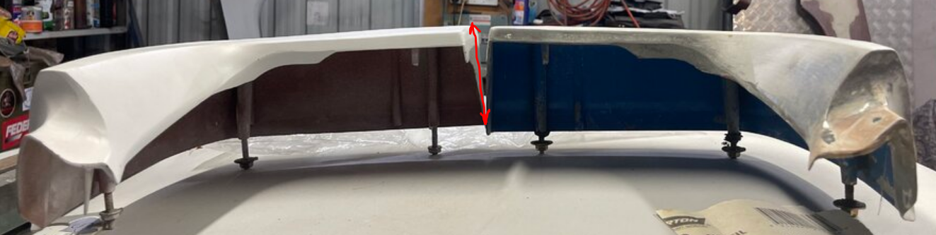
Your complaint is that the right extension sticks out about 1/2" from the panel, and your picture seems to show that the right extension is deeper.
I opened up the trunk of my 69 and measured about 3/16" down from the top , my left is 3.815" and the right is 3.782" deep.

-
Just as an aside, I have read that the early 69 extensions were fiberglass, but mine is metal.
-
-
That engine had around 200hp, 295ft/lbs of torque from the factory with a Holley 4180. You might get 10-20 HP with just a cam change. The Stealth manifold fits well under the hood but again doesn't help more than 10%. The distributor does nothing for HP.
If you want 400HP, that's doable but it will require a combination of carb/EFI, aluminum heads, intake, cam, headers, and exhaust. Something like an Edelbrock top end kit would simplify the choices, or you can blindly pick and choose and hope for the best. If you're like most of us and not an engine builder it will take a lot of research.
-
This is a great build! In your Feb 14, 2019 post with the pictures of the sub frame connectors- are those custom or did you buy them somewhere? Since I've not seen that configuration before I'm guessing they are custom.
-
Thanks Dave,, but I believe that's what they call the "4V Air Valve" and it is 2.53” high according to their email.


351w engine build video
in 1969-70 Technical Forum
Posted · Report reply
Hey guys, I thought some of you may be interested in this video. I don't know if it would fit under the hood of a 69 or 70, but the build basics are the same...besides, who doesn't like engine porn?