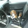
edwards54 15 Report post Posted May 3, 2016 I have been driving my mustang for a few summers and slowly fixing my list of problems. I am focusing now on some cut wires, un attached wire connectors and a non working horn. I have included some pictures to help see what I am working on. There is a set of purple wires going into the engine compartment that are simply cut. The dangle by the master cylinder. Any clue what these were meant for. I have a unconnected wire plug right next to the radiator that is pictured. This was an original a.c. car. Was that plug part of the a.c. Components? My horn does not work. When I jump them with the positive battery they do work. I have them connected to the right wires. The steering wheel is not factory and I have two black wires at the wheel. When connected there is no power going to the horn. How can I diagnose where the problem is with the horn. I do want to thank you for any help or suggestions you have. Bob Quote Share this post Link to post Share on other sites
Midlife 814 Report post Posted May 4, 2016 Purple wires are for the Master Cylinder/proportional valve sensor. The plug near the radiator is for the washer pump motor. For the horn, look at the turn signal connector beneath the steering wheel area and see if the wires are cut. The horn input wire is typically yellow; the output is typically blue/yellow. 1 69RavenConv reacted to this Quote Share this post Link to post Share on other sites
edwards54 15 Report post Posted May 4, 2016 Thanks for the help Midlife. I will take a look at the yellow and yellow blue wires tomorrow. If they are connected do they run to the firewall? I put in front discs a few summers ago and it has a manual proportional valve. Do I need this sensor? Thanks for the help on the washer pump motor. I have been running without that set up and will put it on the list. Thanks again, Bob Quote Share this post Link to post Share on other sites
Midlife 814 Report post Posted May 4, 2016 Only the blue/yellow wire will run through the firewall. The brake sensor is on the master cylinder, I believe, and senses if the two subsystems is out of balance. Quote Share this post Link to post Share on other sites
edwards54 15 Report post Posted May 6, 2016 I checked and the blue/yellow wire runs to the firewall and is connected on the other side. The wires are taped up all the way to the front where they are than separated from the lights and are by the horn. So the wires seem unbroken and where they should be. What would be my next step or what should I look at next? Quote Share this post Link to post Share on other sites
danno 128 Report post Posted May 6, 2016 You had asked also about the proportioning valve. From my understanding, you need both the proportioning valve and the brake sense switch. The system sense when there is an imbalance between the front and rear brakes, and lights the warning light on the dash when there is. It is kind of a worthless system, because if you have a failure in the brakes, it is too late to know about it by some light when you step on the pedal and nothing happens. But it could help, so that is why it is there. The next step for the horn is to connect the blue/yellow wire to +12 volts. You can turn the key on to accy, and touch it to the bolt that extends in the fuse block. That should blow the horn. Then you know the wires to the horn are ok. With an aftermarket wheel, you have a mismatch of wires out of the steering column to the half moon connector that is a part of your under dash wire harness. Do you still have the half moon connector under your dash by the steering column? It has about 12 wires going to it, and the blue yellow should be one of them. Quote Share this post Link to post Share on other sites
edwards54 15 Report post Posted May 6, 2016 Yes that half moon connector is in tact. So do i send the 12 volts through the two black wires coming out of the steering wheel area? Quote Share this post Link to post Share on other sites
Midlife 814 Report post Posted May 7, 2016 No. Apply 12V to one wire at a time. One of the wires should be going to the horns; the other wire is power coming into the horn switch which, when the horn switch is pressed, causes power to transfer to the outgoing horn line. With two black wires, you don't know which is which. Actually, you should check to see if you have 12V at one of the wires with the key in ACC. That line will be the power in; the other line will be the line going to the horns themselves. Quote Share this post Link to post Share on other sites
edwards54 15 Report post Posted May 8, 2016 Today I was able to check the fuses and they all look good. I put 12v to one of the wires and the horns worked. What would you suggest as my next step? Quote Share this post Link to post Share on other sites
danno 128 Report post Posted May 10, 2016 Your next step is to work on the steering column. It looks like you have 2 black wires to your horn switch. Where to these go on the lower section of the steering column under the dash? One of these should go to the wire that you found that blows the horn, and the other should go to +12 volts. Both of these are in the half moon connector. Do you have a voltmeter and/or ohm meter? Do you know how to use one? These are a real cheap aid an figuring out problems like this. Quote Share this post Link to post Share on other sites
edwards54 15 Report post Posted May 10, 2016 Does the power for the horn come from the Light switch? Is this the wrong question? Quote Share this post Link to post Share on other sites
barnett468 418 Report post Posted May 10, 2016 if you put power to a wire on the steering wheel and the horn worked . that wire is good and is the return wire to the horn this means that the other wire needs to have 12 volts all the time so you would have narrowed your search down to just that one wire . all it does is go to full time power. you can use the continuity tester to check it out. you do not have a stock brake system so your brake safety lite won't work without some fixing. Quote Share this post Link to post Share on other sites