Jump to content
Sign in to follow this  
prayers1

Tell me if I have an axe to grind?

Recommended Posts

I bought Mallory Unilite distributor & a Promaster E-coil (internal resister).

I switched the ignition Pink wire to 12 volts. I spoke to several Mallory techs who helped me decide on how to wire this system under the hood & what spark plug wires to use. Installation is very basic, Ignition 12v wire to Pos. side of coil and to red wire on Distributor, Green wire from Dist to neg side of coil, Dist brown wire to GOOD engine ground. That's it!


Since I had an E-Coil, I bought from Jegs a new Mallory Male end Dist cap & rotor and MSD spark plug wires.


I installed a rebuilt 289 and 4 speed toploader. Basically everything under the hood is NEW. We went to do the first run and couldn't get the motor to fire up, it kept back firing and sometimes pretty bad. We went through the basics spark, air & gas and couldn't find anything wrong. We checked Voltage at the coil and even did the module test per Mallory's website and everything was fine. We kept trying to change timing over and over again. Finally we went to see if the Dist Cap or rotor was cracked and found that the rotor had 6 slots for the optic viewing instead of 8. After getting the correct rotor we now find that the module is burnt. I got another module locally for $130, installed it and it went up in SMOKE. We did the module test and it showed 12 v instead of 1.5-2.0 (Bad Module again). We checked the coil ignition and dist side and getting 12 volts. Then we did an ohm's test on the Neg & Pos side of the coil (Primary windings)and it showed 00.2 instead of the factory 1.4. We also checked the secondary windings which was within the factory range of 9.0.


We concluded that by trying to start the motor over and over many times, that it somehow burnt the resistor in the coil leaving an open current and each time a new module was put in it would burn out.


I contacted Jegs and they said that they would replace the rotor with the right one but my beef about other stuff lies with Mallory.


I believe that if I had the right rotor to begin with that no of this would of happened. I would like if Mallory would replace the coil and module, but how do I explain it in terms to be benifical to my cause. As we know the Big Companies can talk their way out of anything, since they are the experts and I am just a weekend mechanic.


Any SERIOUS susgestions and Please dont say "shouldn't of bought a Mallory"

Thanks for your help,

John

Share this post


Link to post
Share on other sites

While I understand your problem, it will be an uphill grind to have them replace those parts.

This is the main reason I stay away from electronic ign systems.

They will say its from a mix and match of parts that caused the problem and you should have checked ALL of the parts before hand.


:001_unsure: on how just trying to start the eng could have caused the resistor to burn out.

And I am running a Mallory dist, but it is a dual point mech adv that works great.

Share this post


Link to post
Share on other sites

I'm really ticked about this. I've been trying to be mindful on my budget to get things done right the first time, so I ask a ton of questions, not for some Company package mixup to cost me more.


After consulting with Mallory, here's what they told me on how to wire the Dist & Coil.

Splice together the 12v from Ignition to Red wire from Dist-then run a wire to the Pos. side of the coil.

Take Green wire from Dist and green wire from Tach, tie them together and runa wire to the Neg. side of the coil.

Brown wire frm Dist. to GOOD engine ground.


My theroy is that from cranking the motor over too long with the wrong rotor shutter wheel, it eventually over heated the Coil and burnt the resistor in it, this allowed a direct 12v source to the Module.


Before installing the 2nd module, I checked for current and had 12 v to the coil with the key on . Then after installing the 2nd Module, I went to check voltage at the module, this is done by turning the key on and you placing a credit card inbetween the optic eye, you should get a 1.5 -2.0 v reading (if 12v it's shot), but when I went to do that, the key needed to be on which it was, then I was to put the pos. Battery cable on, as soon as I did that it smoked before I placed the credit card there. To confirm the Module now reads 12v.


Someone told me that it doesn't matter on the Dist red wire side if the coil had a resistor or not, that a Res. shoud of been between the Dist. and Coil.

Then why would the coil ohms read on the Primary side 00.2 instead of 1.4.


I respect everyone's opinion, so chime in with yours, because I'm looking for the best logical explaination when I call Mallory tomorrow.


Here's a copy of the module instructions. You can see they say no need for a resistor if using Coil 304540.


th_ModuleInstructions.jpg

Share this post


Link to post
Share on other sites

After looking at the spec's of the dist and coil.

Did you use a power filter?


Now I have to ask this, How does the coils built in resistor work for the mod in the dist?

You have a 12v lead to the + side of the coil, And the lead from the dist attached to the + side of the coil.

Having them both on the same lug on the exterior they both are getting the same voltage and spikes. So what is protecting the Mod?


Sorry but I think some protection should have been used for the Mod, and Yes they should have so stated in the instructions.

Share this post


Link to post
Share on other sites

I agree with you.


The question has come up on installing a resistor on the red wire going to the distributor, but someone had said it doesn't matter how much current the module sees it's the voltage spikes that kills the modules. I think the coil resistor is to protect the coil, and I think everyone thinks it protects the module. I'm a little confused myself.


I contacted Mallory this morning. They said to forward the wrong rotor and damaged items for replacement. Will see if they keep their word.

Share this post


Link to post
Share on other sites

Maybe I can supply a little more confusion. There should be no need to put a resistor between the red wire to the distributor. The red wire to the disti is to supply operating voltage for the electronics in the distributor. Unless you are 100% sure the coil has an internal resistor, then the resistor goes between the ignition and the + of the coil. I did some looking, and I could not confirm that your coil has an internal resistor.


I am not sure you will have any luck with Mallory, they are out of control of the way their system is connected and what it is connected to. But let's see if you can figure this out. If you have a bad coil, it will cause the distributor to fail. Likewise, if you have a bad distributor, it will cause the coil to go bad. So you start with one bad part, it causes the other part to go bad. You replace the original bad part, but because the second part went bad, the new part also fails. It is a terrible circle to be stuck in. You almost need to check each part out seperatly.


You should be able to test the coil and distributor independant of each other to allow you to see if each is operating corrently. For the coil, it should measure about 1 ohm between the + and -. If it does, then hook the coil high voltage output ( the big lead that does to the center plug on the disti) directly to a spark plug wire, and put a spark plug in the other end. Clamp the plug to the engine somewhere so you can see it spark. You will be bypassing the distributor completely. Then take a little wire that is connected to the engine ground and touch it to the coil - for a tenth of a second. In other words, just brush the ground wire past the - input. When you do, you should see spark on the plug. It will be faint, so shut off the lights so you can see it.


To test the distributor, you will need a 12 volt light bulb with wires on it. Connect one wire from the light bulb to +12 volts, and the other wire to the bulb to the green wire of the distributor. As you slowly try to start the motor, you will see the light turning on and off. If the motor was turning over as fast as it would notmally to try to start, the light should be dim.

Share this post


Link to post
Share on other sites

Mach1Rider- I will use your advise regarding the vauge instructions if and when it comes time. Hopefully, they will replace what went bad. I've already mailed the items.


Danno- Your a bit more experienced than I'm regarding wiring. I'll see if I can follow you.

I did test the Coil with an Ohm meter at the neg and post coil post (00.2) mallory staes the primary wind needs to be 1.4. As for the secondary windings, placed my Volt Meter on the big center post and either neg or pos coil post. It read 9.0 which is should be per Mallory.


Another question came up if a resistor would be needed if the wires are parralle or in series. This is how I ran the wires: I wired the Ign. wire directly to the RED Dist wire, then ran a single wire to the Pos. side of the Coil. Then I ran the Tach wire to the Green Dist wire, then a single wire to thye Neg side of the Coil. I'm a bit confussed, but how will the Coil Resistor protect the wires if they are wired 12v prior to the Coil. As I see it, there is no other way to do this.


Before the 1st module burnt up, I did confirm 12v at the ign. and checking the module with a credit card blocking the optic I got 1.5 - 2.0. If the optic was BAD it would of read 12v. I believe excessive cranking caused the module or coil to go. Unbeknown to me the coil resistor was shot after the 1st module. I bought a 2nd and was going to test the module per Mallorys instruction video. I installed the module, turned the key on and went to put the pos battery cable on, at that moment, I heard a crackle at the battery pos post andn witness smoke coming up from the module. I checked all of my wires under the dash and in the engine are. Nothing was wrong. I concluded that since the coil was shot w/o me knowing it burnt the 2nd module.


I thought of doing something different. before install the new replacement part.

Getting a Duraspark Dist, a GM HEI module and a TSL Coil. Try that set up and get the motor broken in and all the bugs worked out.


It's not gonna be a race car, so I'm open for suggestions. It is a 289 bored 60 over Cam has 280 duration & 512 lift, 54cc Head w/screw in studs & 194 GM valves, Dual plane Ebelbrock FB4 manifold, 600 Holley DP, 4 speed toploader, 3:55 9' traction lok


Sorry typed in a hurry, didn't check spelling!!!!!!!

Share this post


Link to post
Share on other sites

OK, first on the coil. Ohms checks at these low values are always a bit tricky. You should disconnect all wires to the coil and measure from the big center post to the - input or the + input and you should get about the same for both. About the 9 ohms or so. Connect the leads of the ohmmeter together and read what the meter says when the leads of the ohmmeter are directly connected together. This is "zero ohms", not matter what the meter says. Now connect it between the + and - inputs, and you should get close to zero or a little more. Maybe 1 ohm. This sounds like it is measuring this and so far it is good.


The ign wire to the red disti wire is correct. This single wire then that goes to the positive side of the coil is the one that the resistor usually goes in. So the + side of the coil has a short wire that only goes to the resistor, and the other end of the resistor goes to the red wire of the disti. This all assumes you need a resistor. As I mentioned, if you are 100% sure the coil has the resistor built in, then it is not needed.


Quote "Before the 1st module burnt up, I did confirm 12v at the ign. and checking the module with a credit card blocking the optic I got 1.5 - 2.0. If the optic was BAD it would of read 12v."

Probably true. If you read 1.5 to 2 volts with everything connected and using the card to block the light is sounds ok. If you remove the card it should go back to 12v.


quote "I believe excessive cranking caused the module or coil to go. Unbeknown to me the coil resistor was shot after the 1st module."

You should be able to read the resistance of the coil resistor. The manufacturer should have a specification for it, they are usually about 10 ohms.


quote " I installed the module, turned the key on and went to put the pos battery cable on, at that moment, I heard a crackle at the battery pos post andn witness smoke coming up from the module. I checked all of my wires under the dash and in the engine are. Nothing was wrong. I concluded that since the coil was shot w/o me knowing it burnt the 2nd module."

This could be true. Try the light bulb test I mentioned on your existing or new module.


Good luck, I will check back on this...

Share this post


Link to post
Share on other sites

Danno- Sorry I can't do the test light test. Yesterday, I mailed the coil and 2 modules back to Mallory for replacement.


COIL- Promaster E-Coil 30450. If you copy and paste and look at Summits site, I read Primary resistence of 1.4. When I tested with the coil at it's Neg & Pos terminals, I did this with the coil disconnected on and off the vehicle body, My readings over and over were 00.2. That would indictae to me an open and full charge of 12 volts all the time. I did check the Center post to either Neg or Pos on the coil. If I'm correct that is measuring the secondary windings, I got 9.5, this is with in Mallorys range. I did my own Ohm test and it does go to ZERO.


I am not that schooled in wiring, but learning a little at a time. Common sense tells me that if the Red Dist wire, & Ignition wire are joined before going to the coil that there should be 12v all the time to the module. See post #3.


There are so many trains of thoughts out there. One is that the resistors in general have nothing to do with points or modules. Their only purpose is during cranking when the starter volts drop, there is no longer 12 volts at the ignition, therefore if there is a resistor tied w/in the ign wire the coil can work with 8 volts.


Also, what do you think about a resistor in between the joined section of the red wire to the dist? Would that be a safe gaurd for the module. Or would it be safe to tie in a resistor at the Ignition wire.


Eventually, I would like to get this Mallory Ignition system working when the replacement parts come back and I say that with my fingers crossed. I don't think Mallory should give me any problems. The Product Manager on the telephone was understanding and willing to rectify the problem.


All opinions welcome!

Edited by prayers1

Share this post


Link to post
Share on other sites

I looked at the details for the 30450 coil, and you are not supposed to need a ballast resistor. So you should be good to go. When you used the ohmmeter and read 0.2, that is a short, not an open. The + and - inputs are shorted together inside the coil. If this happens, it will blow up your distributor pretty quickly. I guess you know that.


From the center post to either the + or - should give you about 9 kiloohms. 9 kiloohms is the same as 9000 ohms. Your ohmmeter probably adjusted the scale automatically so you thought you were seeing ohms, when in fact it was kiloohms.


You should be fine with the red disti wire, ign switch, and coil + all tied together in the same wires. Don't worry about the resistor. You had it connected correct, just one bad part caused the next part to fail. When you replaced the bad part, because the second part failed initially, it caused your replacement to fail. If all of them work, you should be in good shape.


By the way, the reason most cars have a ballast resistor is that this is normally connected to teh coil +. When the car is starting, the ballast resistor is bypassed so you get a hotter spark. With your coil having an internal resistor, you will have the same spark during start that you have during run.

Share this post


Link to post
Share on other sites

Are you saying that the + and - Coil terminals melted together. Is this what caused the modules to go. So, without me knowing, when I replaced the 2nd module, I figuered to test the voltage at the module by blocking the optic to see why bhe 1st went. I turned the key on and went to connect the Pos. batt. cable, it crackled and I saw the module smoke.

You stated "The + and - inputs are shorted together inside the coil. If this happens, it will blow up your distributor pretty quickly. I guess you know that. "

I didn't know that. Then why didn't blow up? What caused the new coil to fail. Can excessive cranking be the cause. As you may recall, I was given the wrong rotor, a 6 cyl rotor that has 6 windows instead of 8 for an 8 cyl rotor. I was cranking and cranking the motor trying to get it to start.


My thinking was that the resistor failed within the coil and was sending too much voltage to the module.


If I understand you correctly, the Coil went bad 1st.


Is it wise on my 2nd time around, to install a filter on the Distr. red wire, right before the dist.


If my understanding is wrong please advise. I need to understand why this is happening. I do appreciate your time and advise. Thank You!

Share this post


Link to post
Share on other sites

Yes, it looks like your + and - terminals were melted, or shorted, together because you measured 0.2 ohms. I am not sure which part failed inititally, it could have been either. When the first failure to occur, it caused the other part to go bad. What caused the new coil to fail was because your disti module was bad. It is very likely that if either the coil or disti is bad and you connect the bad part to a good one, itr will cause the good one to also fail.


Something failed within the coil, either the resistor or wires, it could be either.


The 6 cylinder rotor and excessive cranking should not make any difference. Neither of those should have caused anything to fail. What could have caused a failure was something miswired, even for a second, with the voltage is on.


What filter are you discussing? You mentioned on the 2nd time around to install a filter. What is this? If you replace both parts with new, and wire it correctly, it should work. Just in case, you might want to try the test light thing I talked about. It is a safe way to validate it is all connected correct.

Share this post


Link to post
Share on other sites

Everything was new, even the wiring. Even though I'm just learning, the Distributor wire diagram is very easy to follow and because of my uncertainty, I spoke to Mallory techs to confirm. The Ignition wire was new coming from the KEY plug-in-terminal to Coil. If I have had to do it all over, I would wire it the same way.


Hypothetically, How can a module burn out a Coil. It should be vise versa.


Someone had told me about this filter. I had never used it, maybe they were thinking a resistor in-between the Dist and Coil.


In the very beginning of the start up, We immediately encountered start up problems (due to the rotor). We checked voltage at the Ign wire to Pos side of Coil, Power from Coil to Dist and power to module when blocking the optic with a credit card. All checked out. What caused the 1st module to burn out. I would guess from excessive starting either causing the coil/resistor to burn out or voltage spikes.


What was very obvious and wasn't there before and during our attempts to start, is when the 2nd module was installed, I then turned the key on, then placed the Pos Batt cable on the Battery. In that instance, the Batt cable krackled and the module smoked. I know this is like a Doctor trying to diagnois a problem over the telephone, but I need an logical explaination to give Mallory to warrant my parts and to prevent this from happening again. If you had to give a diffenent answer, what happened when the 2nd module was installed.

Share this post


Link to post
Share on other sites

You could use the excuse that the 6 cylinder disti caused the coil to fail. You replaced the disti module without knowing the coil had failed. Then you replaced the disti module with the right one, and because the coil was bad, it caused the new disti module to fail.


Your hypothetically thing about the module buring the coil is not hypothetical, it is very real. The output from the disti that connects to the coil is normally either a short to ground (when the coil builds up a charge) or an open ( when the spark occurs). If the module is shorted to ground continuously, it will overheat the coil and can ruin it.

Share this post


Link to post
Share on other sites

I'm sorry that I'm asking a ton of questions. I just don't want to have a repeat. The more I understand the better I can prevent it.


I'm trying to think how the module could short out the coil. First you have to apply some white paste to the bottom of the module, Then bolt it with 2 screws to the dist. housing. Of the 3 wires coming out of the Dist. one of them is bolted to the block for ground.


I appreciate your time and attention to my concern!

Thank you!

Share this post


Link to post
Share on other sites

I don't know how the module could have shorted out the coil either. If you had it miswired, that could do it. Other than that, it should work. If you have a light bulb in a socket, you can do the light test. It might be worth buying them if you do not have them.


By the way, what part of Arkansas do you live in? There used to be a guy about 50 miles northeast of Little Rock with a whole bunch of old Mustangs that he would sell parts from. I bought parts from him back in 2003. Do you know of htis guy? Is there an Army base around there? I think he was by the army base.

Share this post


Link to post
Share on other sites

Long story short-

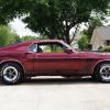
My 1st car was a Mach 1 428 CJ, 3 speed slap stick, 4:30 rear. I it bought for $900. Only picture I have is below. At 17 yrs old, I totaled it, then went to college.


So, at mid-age I bought a Fastback to try to duplicate the looks of the 1st one. I can't afford the cost of the 428 drivetrain, so the 289 4speed will do. I didn't even know about this Mustang Guy, until a friend told me about him. Wouldn't you know, he's 3 miles form me and has just about any part I would need. He has 3 warehouses full of old parts, Scott Drake, Motors, Rears & Body Panels and other stuff. He trys to be competitive but gives me a break, so I can't complain. He's a real nice Guy and will try to work with you or even trade on parts.


If your looking for something, here's his info:

ADCO Mustang, Eddie Adcock, 870-741-7525


I do have a test light and will look at your prior post.


th_LastScan.jpg

Share this post


Link to post
Share on other sites

I am wondering if this is the same person, the odds are that it is. I thought he was northeast of Little Rock, but maybe not. I will look at my paperwork tonight. If it is the same guy, then you know how valuable he is. 7 years ago I talked to him about selling on ebay, and he was not at all interested in that "interweb stuff".


Let us know when you get your new parts and I will walk you through testing them with the light bulb, if needed.

Share this post


Link to post
Share on other sites

Sorry to burden you guys with my problems, but I have a MAJOR one now.

Instead of waiting for Mallory to get back to me about the replacement parts, I picked up a new SBF HEI Distributor. I went to start the car and nothing but a click. I double checked my connections (new battery) went to do it again, as I turned the key my voltage gauge showed 12 v, but when I went to turn the key all the way there was a click then ZERO on the voltage gauge, in fact no power anywhere. I thought maybe the solenoid, so I replaced it. I turned the key on, voltage gauge was 12v, then went to jump it with the solenoid, again CLICK now I hear that it’s coming form the solenoid. I am not getting any power to the ignition 12v wire. I did a continuity test of the brown wire from the solenoid to where it comes out of the fire wall and before attaching to the ign wire and that was good. I can turn the motor over with the solenoid, but not key. If I leave a test light on the ign 12v wire and the other end on the batt, the light will light up if I crank the motor with the solenoid. I even disconnected the alternator to see if any change NONE. Right now NO POWER to anything, but I can still turn the motor over with the solenoid.

What’s Up!!!!!!!!!!!!!

Share this post


Link to post
Share on other sites

You could have something that is shorting out the ign wire from your key switch. Disconnect all the wires to your ignition and see if you can get the motor to turn over. If that does not do it, it sounds like you have a bad connection. You will have to start the troubleshooting procedure if that is the case.

Share this post


Link to post
Share on other sites

What do you mean. Pull the connector from the ignition switch and try to turn the motor over with the solenoid/screwdriver?


Good News!

Here's an email form Mallory-

John-


I have received and processed your warranty request for the coil and modules. They should leave the factory by Monday 10/24 at the latest.


Thank you,


-Steve

Share this post


Link to post
Share on other sites

Well I went to install the HEI and the housing hits the Edelbrock 4BF Intake front runner. Then a friend lent me his which has a longer shaft, it still hits the intake.


Too Bad, I really wanted that setup to work. I guess I'll have to wait for the Mallory parts to come in. I'm reluctant to use it again , for fear of a repeat incident.


danno-What do you mean. Pull the connector from the ignition switch and try to turn the motor over with the solenoid/screwdriver?

Share this post


Link to post
Share on other sites

Join the conversation

You can post now and register later. If you have an account, sign in now to post with your account.

Guest
Reply to this topic...

×   Pasted as rich text.   Paste as plain text instead

  Only 75 emoji are allowed.

×   Your link has been automatically embedded.   Display as a link instead

×   Your previous content has been restored.   Clear editor

×   You cannot paste images directly. Upload or insert images from URL.

Sign in to follow this  

×
×
  • Create New...