
RPM
-
Content Count
6,454 -
Joined
-
Last visited
-
Days Won
240
Posts posted by RPM
-
-
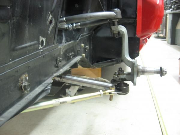
Several years ago I thought about building a chromoly tube front suspension using coil over shocks like I'd seen on many hot rods. I considered the Mustang II, but didn't really want to cut up the car. I figured by using the basic stock suspension design and pick up points (with Shelby drop), but using tubing and quality coil overs, I'd have something that rode well, looked cool and different. I knew that with my basic skills I didn't want to pay someone for something I could do as well, and for a lot less.
It didn't take to long to pick the materials and components I wanted to use. One day at the grocery store while looking thru Mustang mags I ran across a write up on the Ron Morris front coil over suspension. Holy crap, mine looked almost identical. About the only difference was he used a 1" lower control arm, and I had a 1-1/4". I felt confident mine should work out OK.
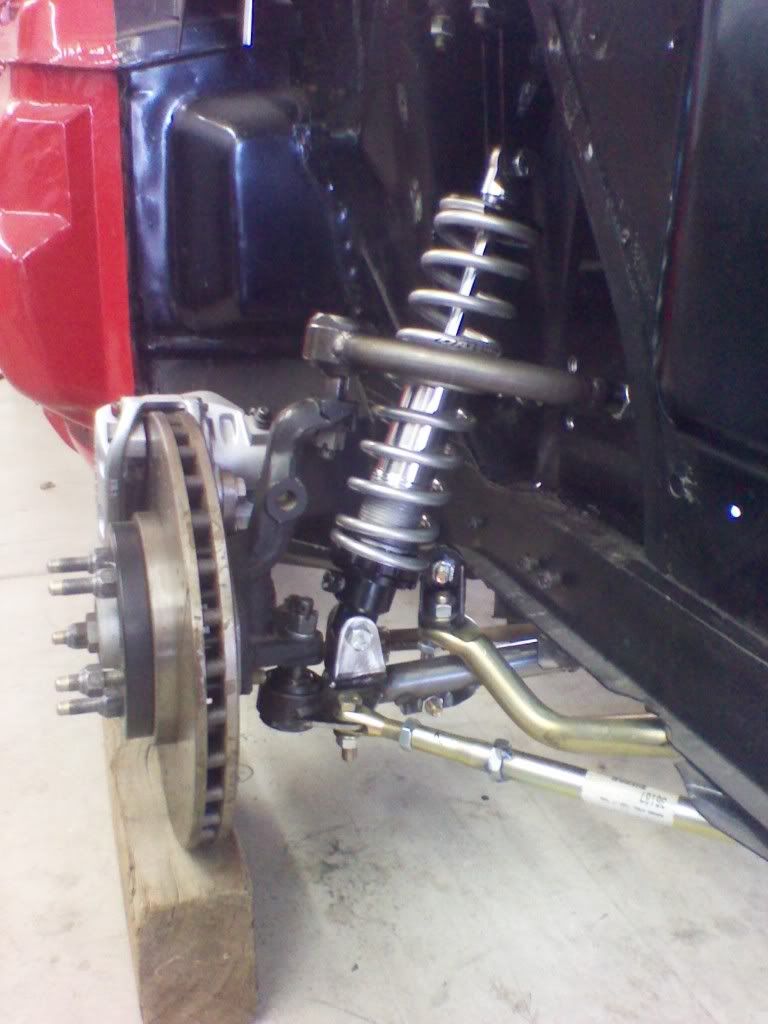
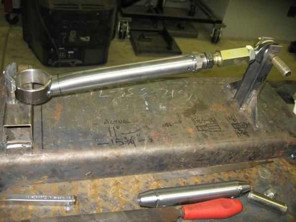
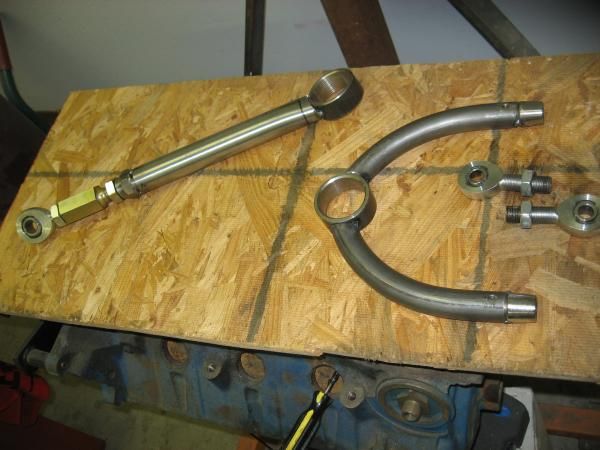
I bought the front and rear 4130 tubing from The Chassis Shop. They bent the upper 1" x .083 wall arms. I used the stock arms to build jigs to fab the tube arms. I used tube adapters to attach rod ends. The strut arms were originally 1" swedged tubes with 5/8" ends. I had a change of heart and wanted to use a 3/4" clevis. The new strut rods are 1-1/8" x .083 4130, as that is the smallest size tube I could use with 3/4" thread rod ends.

I used a piece of hex bar to make the UCA pivot shaft. Center drilled it, tapped it 1/2" -20 and tapered the ends all on the lathe.
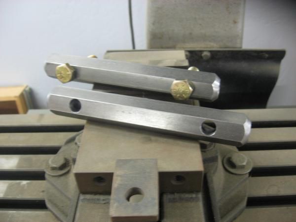
I made the sway bar link from mild steel hex bar. I center drilled it on the lathe, then tapped them for left and right hand threads.
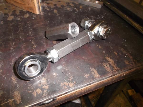
Front upper coil over mount.
-
Thanks waketek. My golf game and fabricating/welding and such have something in common. I know what I'm capable of, I always expect my best results, and rarely am I satisfied with the outcome. Only saving grace with this car is anything I do to it, is better than the factory did.
Bob
-
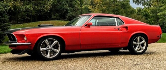
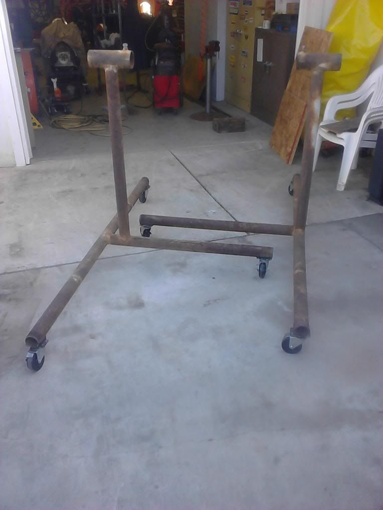
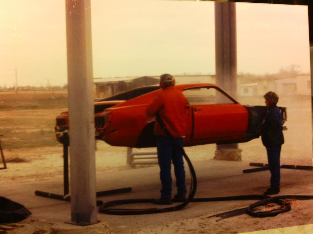
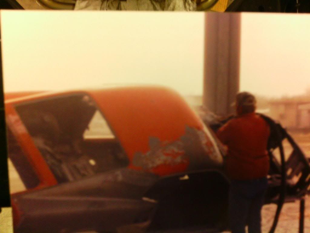
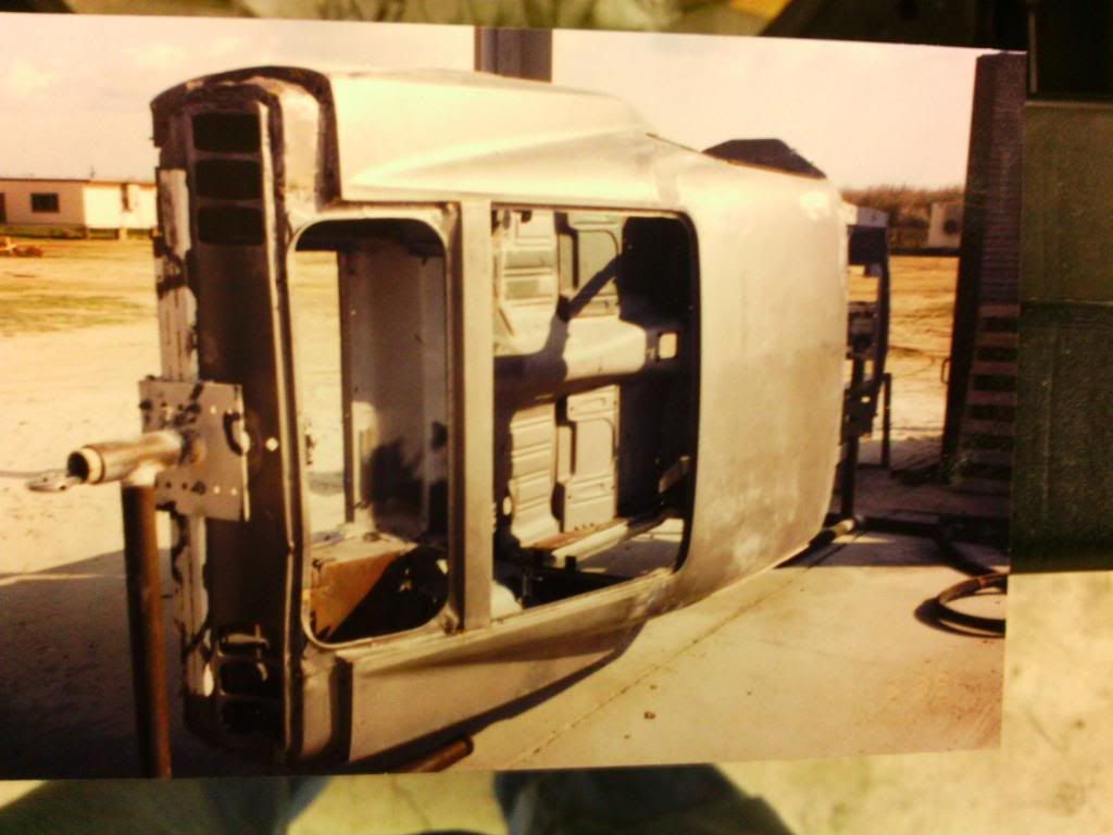
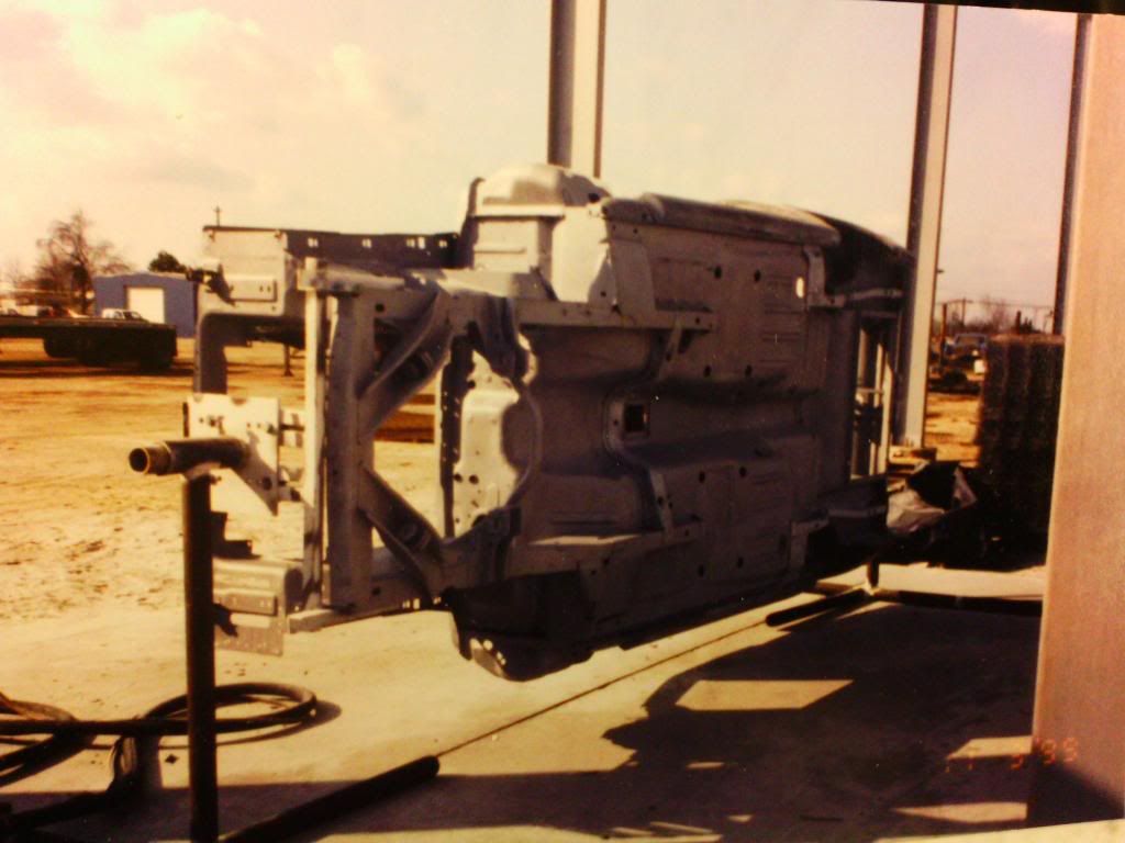
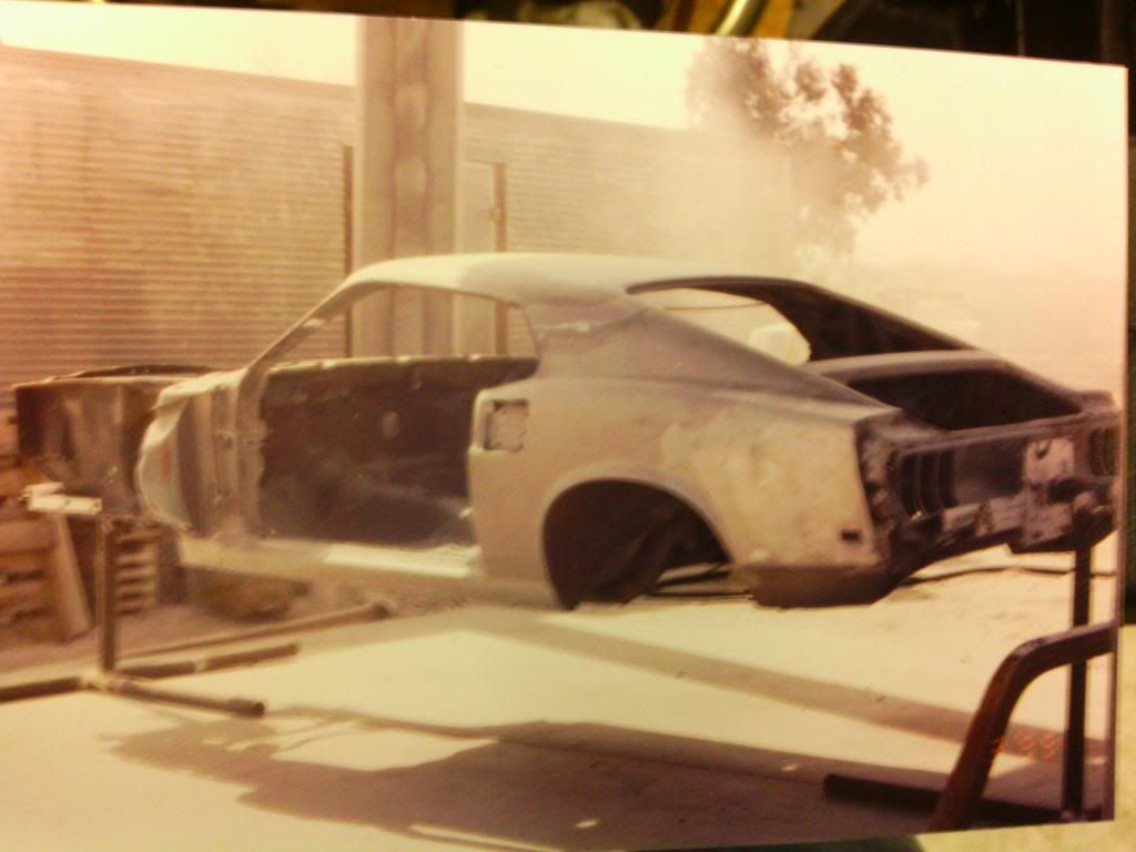
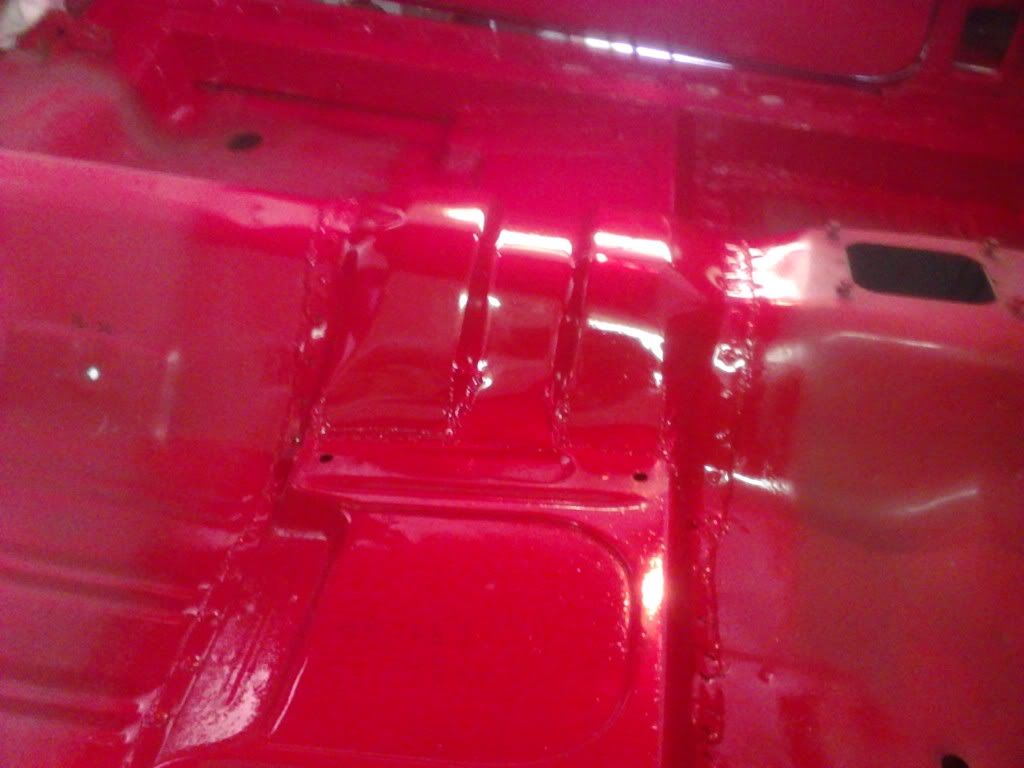
Should've started this thread with these pics, but just relocated them after many years, 5 moves and 2 divorces! Any who, back in 1998 or 99, the car was running and had about a 2 yr old paint job in Porsche India red. The trans leaked fluid bad and as I was filling it with the car running, it started hauling ass in reverse. It hit a faucet spigot with the right quarter, and pinned a concrete mixer against a gate post. Nice, didn't realize it was in reverse. But I do NOW use the parking brake!
Figured with the damage, might as well do a total refurbishment. I built this rotisserie out of materials on hand, stripped the body completely and had it soda blasted. Plastic baggies are nice to label parts in, but mine sure didn't last 10-12 years.
Bob
-
Speaking of buening's motor mount PDF file, I cut out some steel and made a set. I considered using 6061-T6 aluminum for the mounts. Seeing how I've made just about everything twice on this car, I may do it once I've got it on the road again.
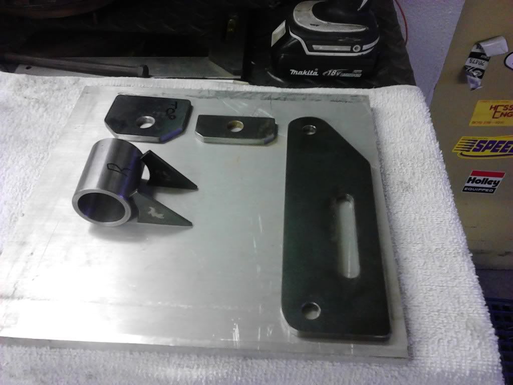
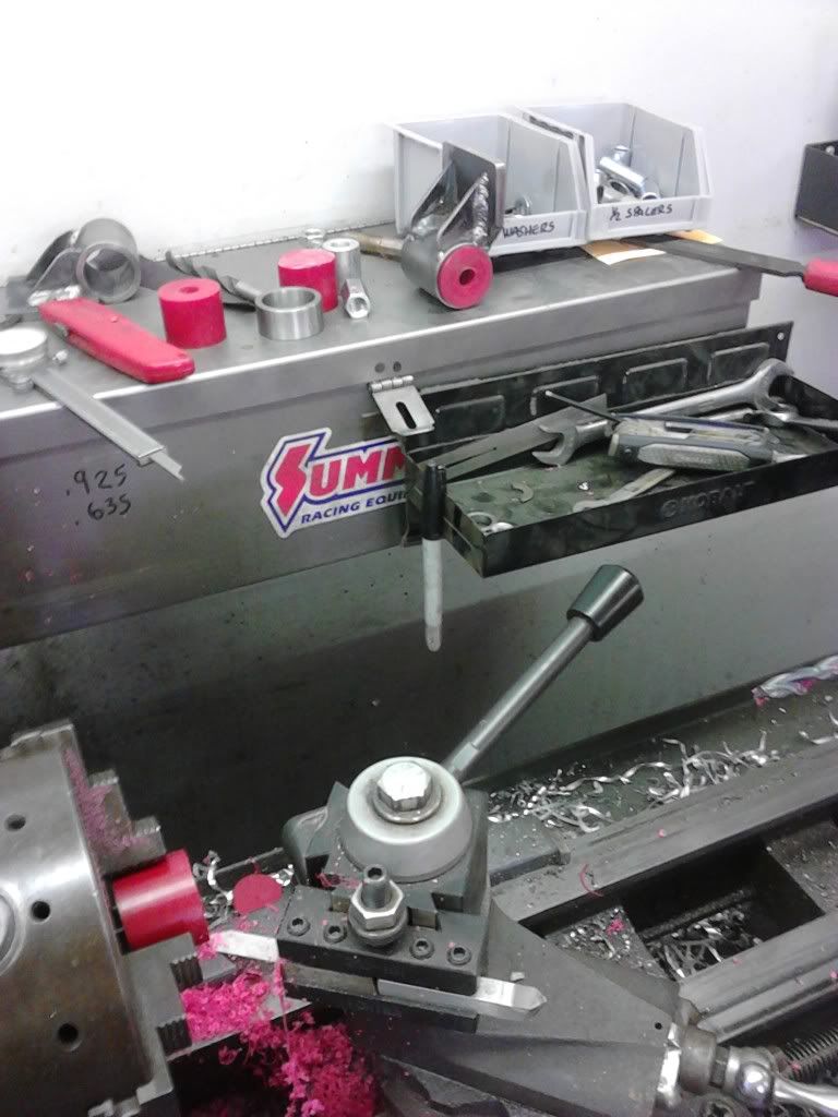
I had a piece of polyurethane rod on hand and turned it on the lathe for the bushings.

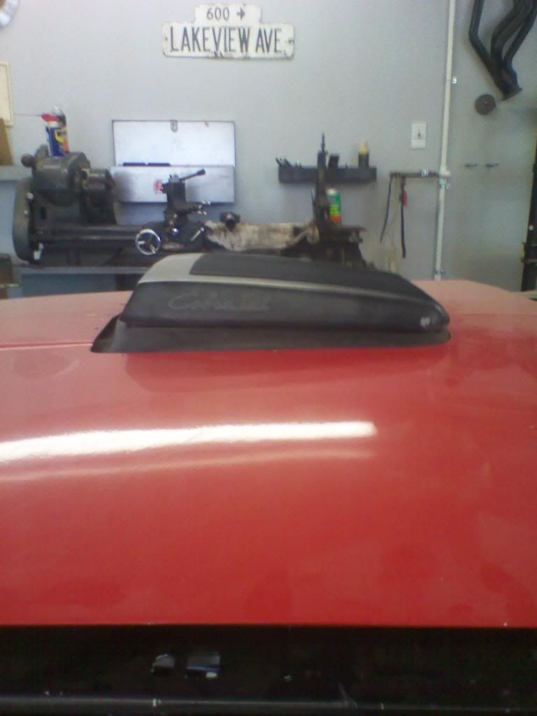
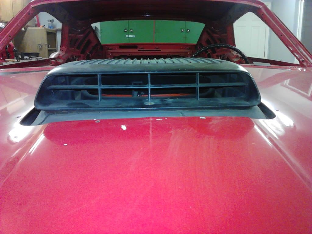
Since I was guessing on how low to drop the engine for the shaker to sit in an acceptable position thru the hood, I used a spacer between the frame mount and engine mount pieces.
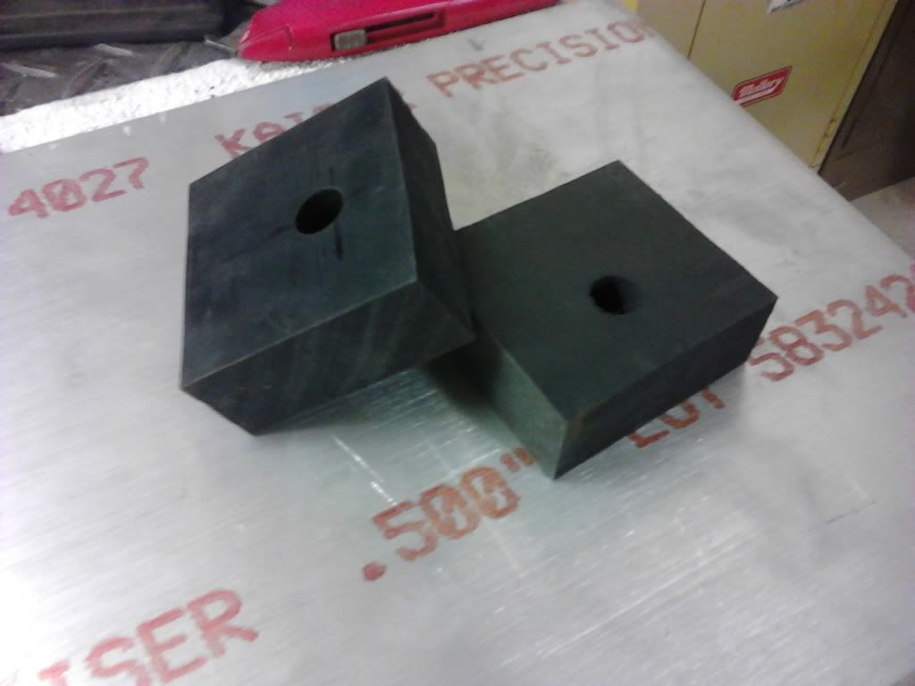
I made the first spacers from aluminum, and a second set from pieces of 1/4" rubber which were glued together.
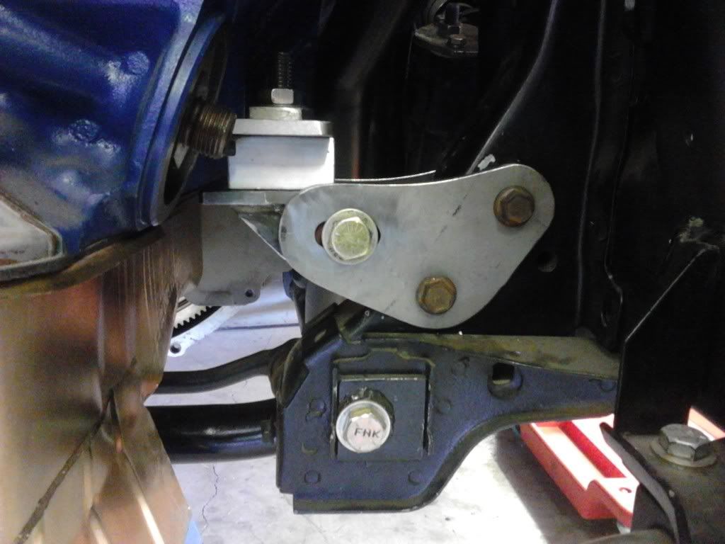
The before and after pics.

Thanks buening.
Edit: I later used a 1/4" thinner spacer and lowered the shaker for a nice fit.
-
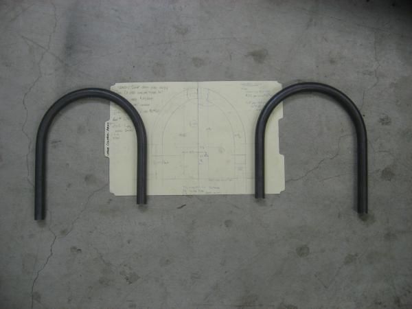
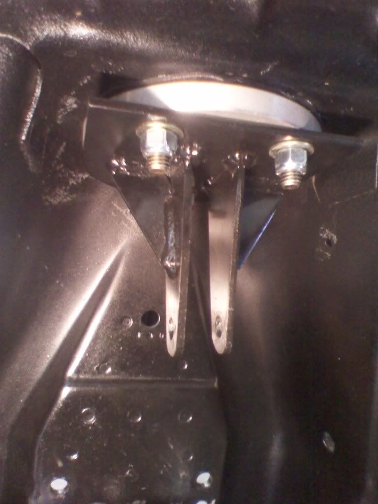
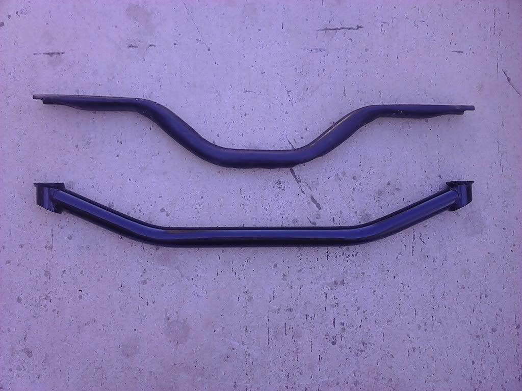
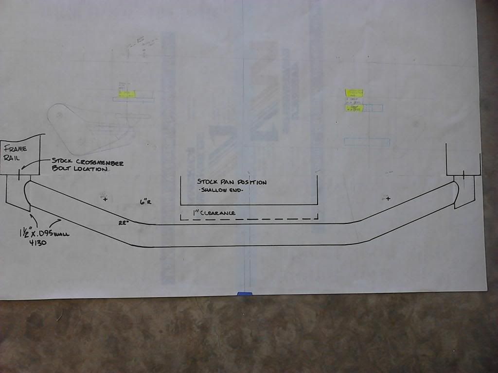
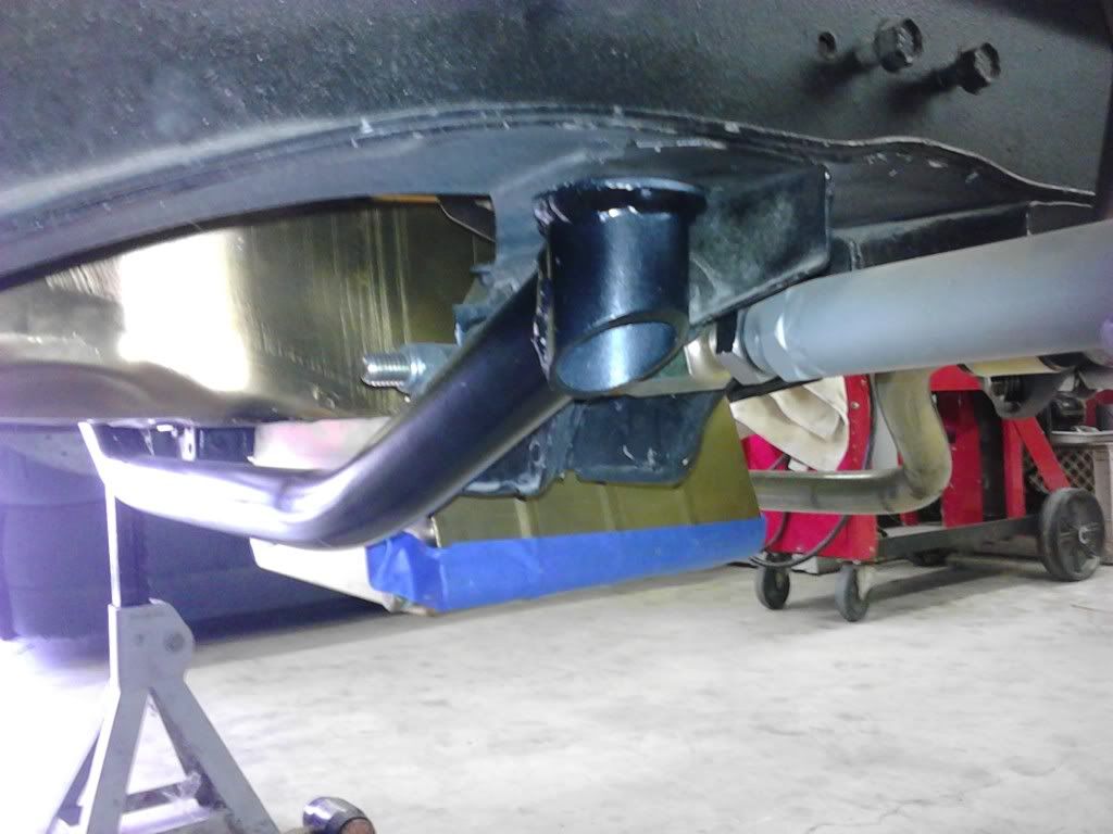
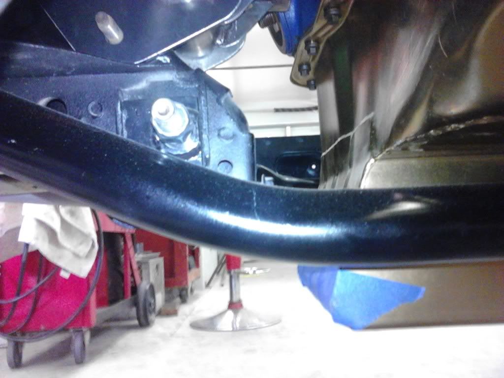
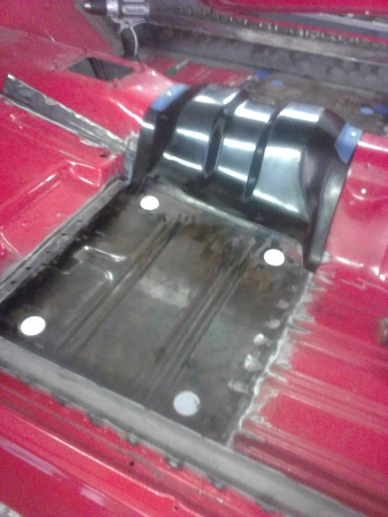
This was covered in another thread, but I thought I'd document it on my build thread. In order to lower my shaker to fit the hood, I considered milling the intake carb plate or lower the engine. Since I really liked buening's motor mount plans, I decided on lowering the engine. For my engine combo the stock front cross member design wouldn't allow the engine to be lowered. Why not make a new cross member?
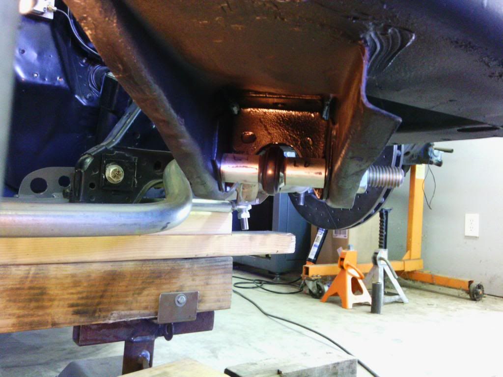
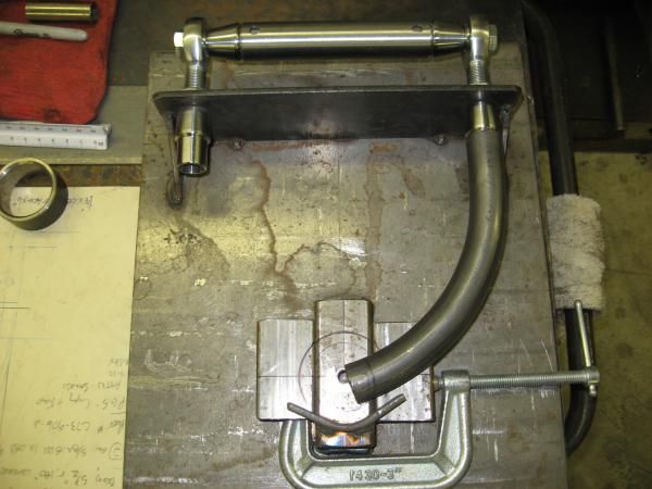
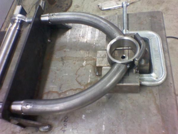
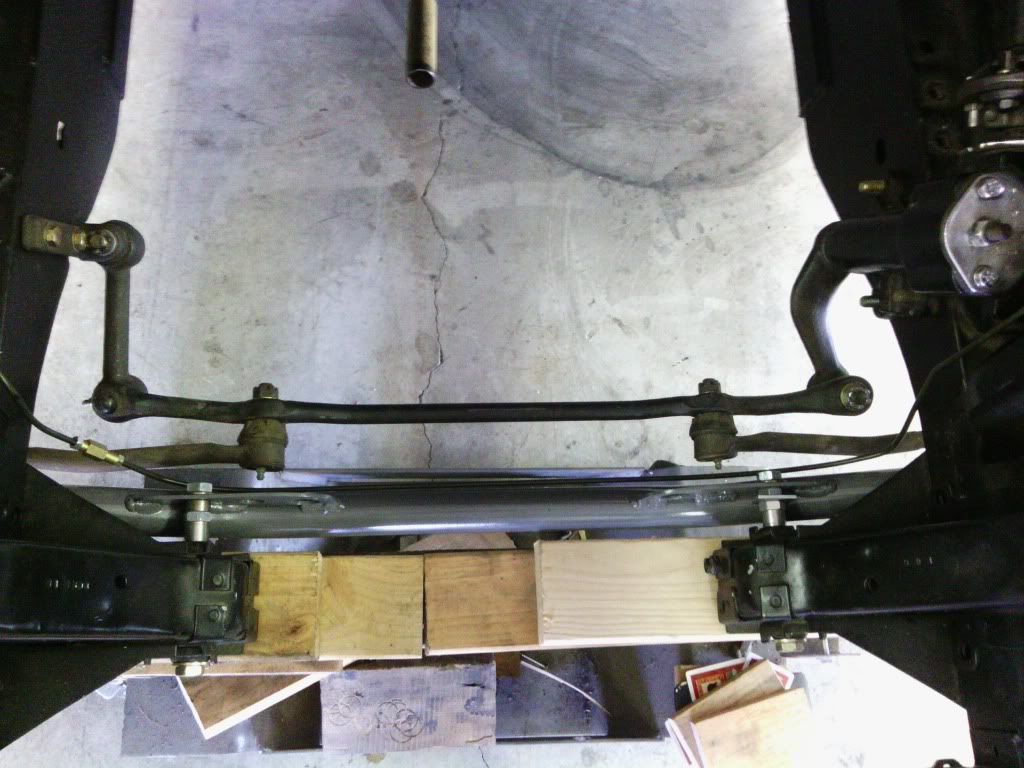
After crawling under the car and eyeballing things, I came up with a design that I thought was a good one. It would have only 2 bends as opposed to 4 for the stock, made from 1-1/2" 4130 rather than mild steel for stock, and have better looking tube mount ends vs crushed tube ends. I drew up full size plans and took them to a local race car fab shop to bend the chromoly tube. I trimmed the ends, tacked them in place while on the car, then removed them for final welding. I normalized the cross member after welding.
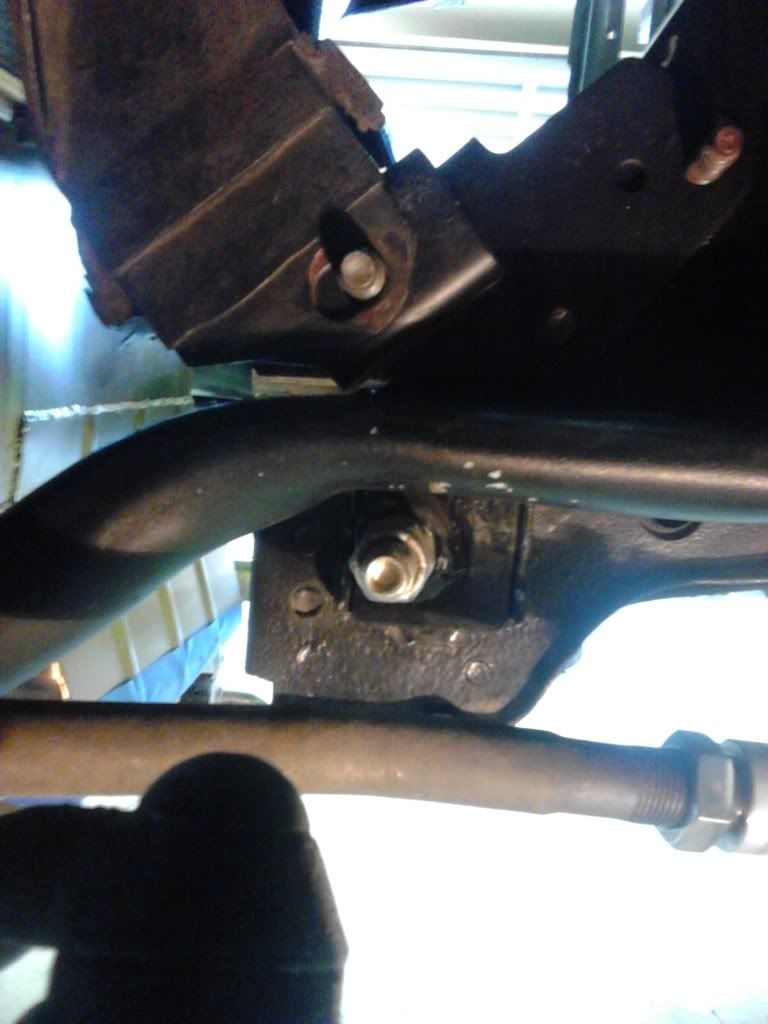
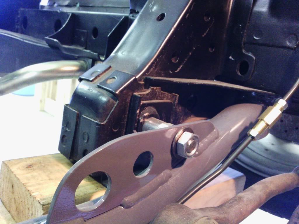
I had it installed for a couple of weeks before I decided to add the Shelby tie in mod to the lower control arm mounting bolt.

Bob
-
Back in about 2006 I bought an Air Ride rear cradle as the base for a triangulated 4 link QA1 coil over suspension. For the control arms I made them from 1-1/4" x .095 wall 4130, Tig welded and normalized, tube adapters for 3/4" QA1 xm rod ends.
I made the lower shock mounts adjustable, and they bolt to the stock spring pad on the rear axle. After assembling I could see something wasn't right. Turned out the upper left coil over mount was 3/4" off. Nice. I could have eye balled it closer than they did. By the time I noticed screwed up mount, Air Ride had been sold to Chris Alston. Should have made my own rear cradle.

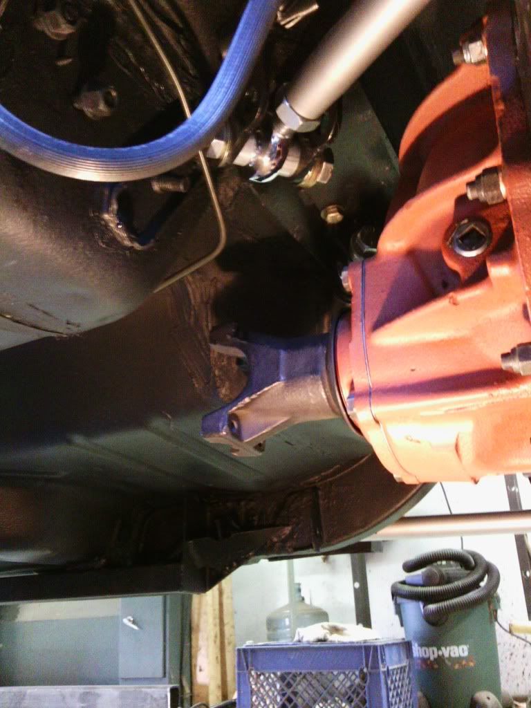
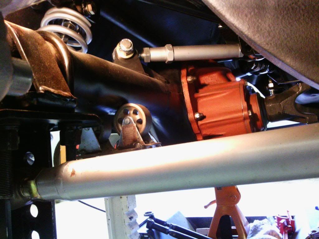

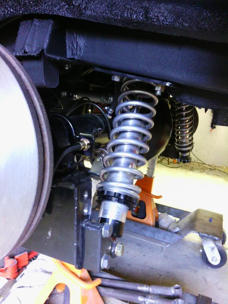

Rear lower coil over brackets prior to welding.
Bob
-
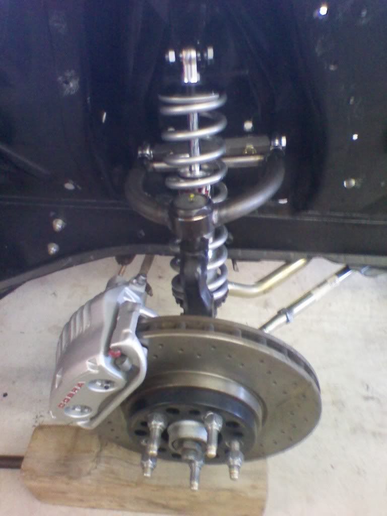
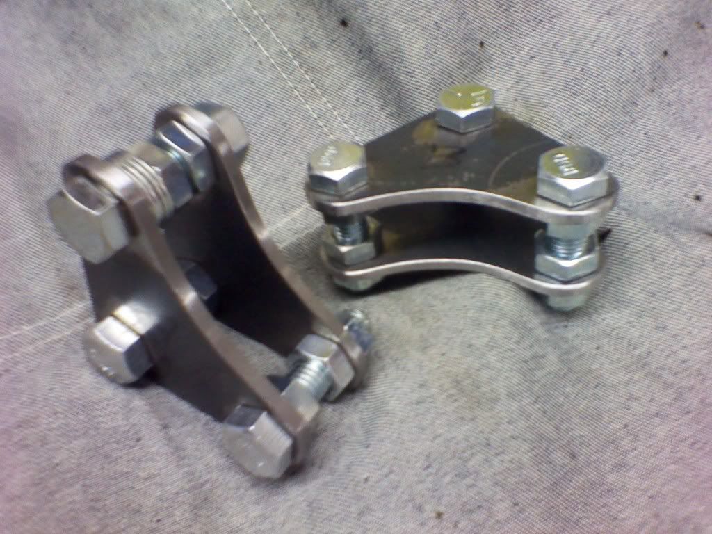
Had a pair of 70 big bearing drum spindles on hand but didn't know I could use my 69 hubs with different bearings. Doh! I had already made brackets to mount 13" 01 Cobra discs to my 69 disc spindles, but when I learned of the needed bearings I made some brackets for the 70 spindles.
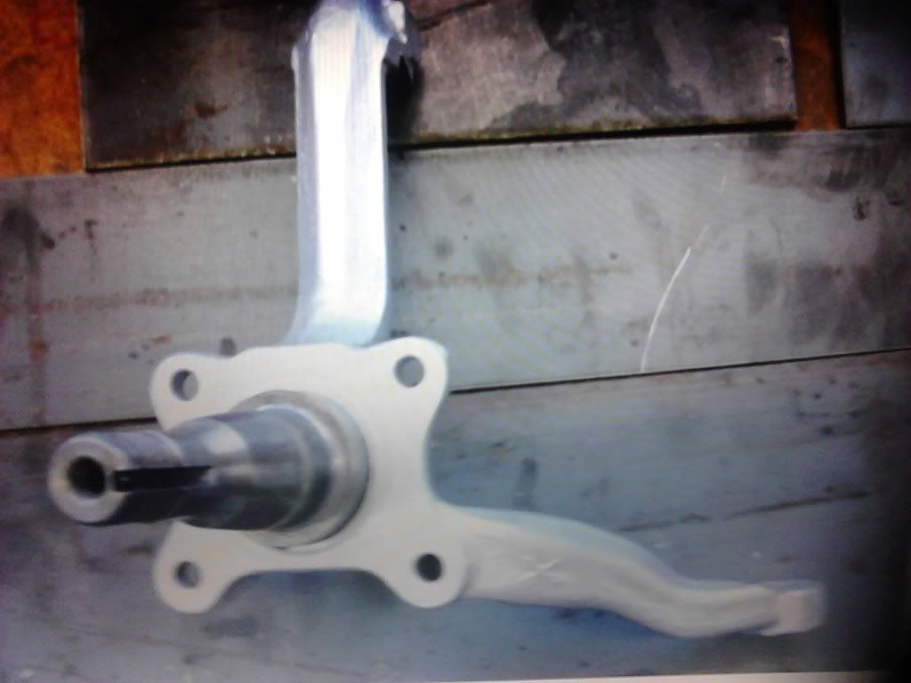
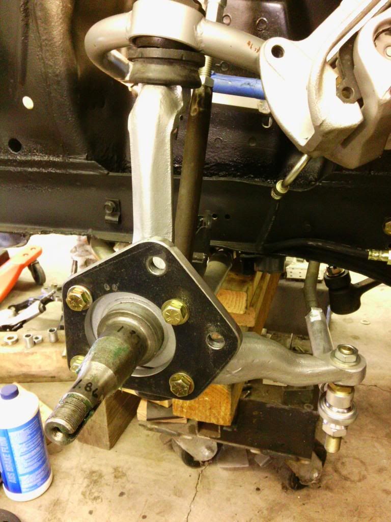
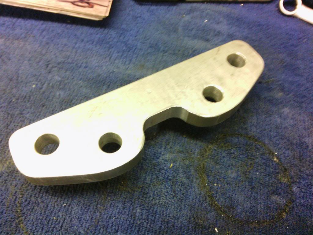
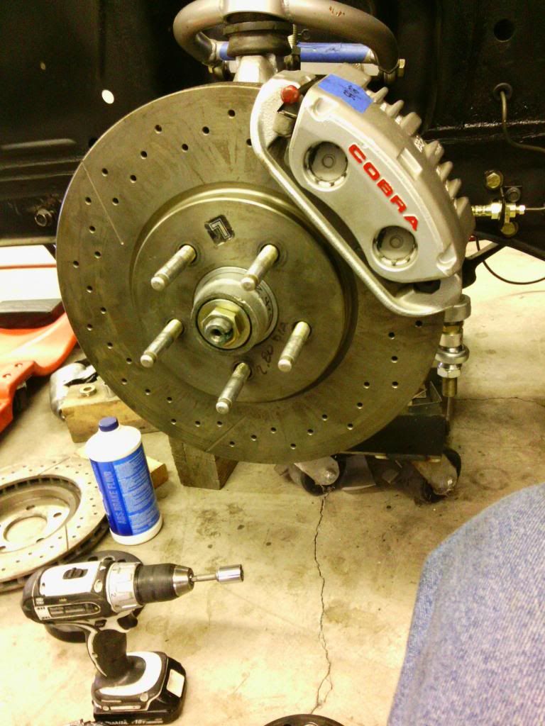
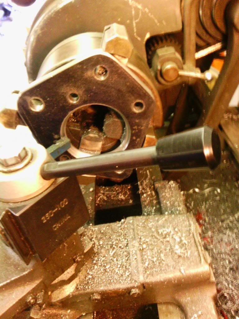
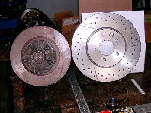
This is why I went with the 13" Cobra front brake. OEM vs 01 Cobra :)
Bob
-
Well, I guess you can teach an old dog new tricks.
Suppose I'll start with the convertible seat risers. As others have done, I spliced the fb model from NPD onto my stock seat risers. Since I had them out with the intent to install the one piece convertible riser, I moved them back 3/4" for leg room. I also installed some self fabbed convertible inner rockers.

-
I just did it on my '69 TA clone racer. I copied that yellow car above, which is here in Houston as well. Its not too hard if you can weld. Here are his pics:https://1970mustangvintageracer.shutterfly.com/551
I'll try and post pics when my car gets rolled out into daylight. Right now I am installing the rear bulkhead panel and rear roll cage legs.
Dude, post up the roll bar tab pics! Pleeese :)
Bob
-
Mine is 1-1/8". My understanding is 69-70 is 1-1/8 and the earlier were 1". Don't know what year they changed.
Bob
-
Dang, I didn't know Debby Downer posted here :) Nice find! He lives in Omaha,, which last time I checked is a good sized city with plenty of buyers. If an out of towner buys something, they deal with shipping. That is if he wants to sell anything.
Bob
-
Great minds think alike!
I just walked into the house from the shop after painting it with spray Rustoleum. Put them in the oven to dry :)
Bob
-
Non a/c or concourse car. The flapper vent piece and heater core surround frame weren't painted on mine, probably all. You guys that have gone thru them, did you paint them? If I don't, I'll be long dead by the time they rust up anyway.
Bob
-
Coils? What coil? Just kidding, yeah it looks fine. Famous last words :)
Bob
-
Back around 12-14 years ago, one of the magazines did an aluminum head comparison. They bolted on AFR 185's and gained 75hp on the dyno. I don't think you can go wrong with any of the big names.
Bob
-
I'm in the process of rebuilding my heater. It worked fine 14 years ago when I tore down the car, and decided while the car is apart to get a new heater core. I was looking at what my NPD catalog calls the "Resistor heater switch" and wondered if I should replace it also. Do they go out often? Should I replace it while I'm at it? Is OEM better than after market? BTW, NPD only shows 65-67.
Bob
-
I have to strongly disagree with you. The leaf springs need replaced. They are a little more than flat/straight.A little more than flat is more arch than the GT350 had. Click link to see pic.
http://s782.photobucket.com/user/robertpmcdougal/library/Mobile%20Uploads?sort=3&page=1
Bob
-
Thanks. The rollbar has been in for about a year. The yellow is just tapeIs it documented here? I looked but didn't see anything :(
Bob
-
Very nice! Did I miss it when the roll bar was installed?
Bob
-
Nice. You'll like those bump steer studs, should be able to eliminate nearly all toe change.
Bob
-
Hmm... when I called NPD they said the hardware was a bolt. I didn't even think about it being an eccentric bolt. Glad it worked for you, it sure looks good under there!
I totally screwed up on my earlier post about the eccentric bolt path. Doh!
Bob
-
have you tried to use the crossmember that NPD sells?No I haven't, but I do like it's design. I think you'd need several eccentric exterminator plates made to adjust the lower arm correctly if the tie in plate is used. Obviously the tie in plate doesn't need to be used, but I think they are reflected in the $200 price. So might as well use them.
Bob
-
If you're planning on getting the NPD unit, be aware the the stock eccentrics will only align with the lca in the full in and out positions if you use a longer bolt and tie into the support plate.
Bob
-
I'm liking this car. Nice to see she's got some hips again. A lot of those wheels would fit right in on our cars. I hope it doesn't look like crap in person.
Bob


Rear quarter replacement
in 1969-70 Technical Forum
Posted · Edited by RPM · Report reply
Couple different ways it can be done depending on the location of the damage. Anywhere probably 8-12 as a wag. Been several years since I've written a sheet. Paint time around 3. Plus materials. Somebody here surely must work at a shop with correct time.
Edit: hell, your car looks great in your album! New damage?
Bob