
RPM
-
Content Count
6,454 -
Joined
-
Last visited
-
Days Won
240
Posts posted by RPM
-
-
To continue on with what RPM recommended you could also do a 2011+ 13.2" GT upgrade. Steve makes a bracket that works for the 2011+ GT rotor and caliper.Currently you can get the rotors and front calipers from Roush as take offs on their ebay page. I paid $50 for 2 front 2011+ 13.2" rotors and $75.00 for 2 front GT 2 piston calipers.
Of course I have a 69 with Granada front brakes so I had to find and get 70 front drum spindles and hubs but I found both used and spent about $120.00 for those.
Doh! I looked at roush's website for take offs before I posted but didn't see any. I forgot they were on eBay. That's the route I would go. Killer price and new!
Mustang Steve says to try it with the stock 69 prop valve, to add an adjustable one if needed. Wildwood has one for about $50.
Bob
-
You can do the 13" Cobra brake conversion from Mustang Steve for =< the $750 from csrp. Steve's brackets are about $250 iirc, used calipers from http://www.car-part.com for $75 each, rotors around $100 each hoses and pads, bam!
Bob
Edit: oops, just sunk in that you already bought the csrp kit.
-
Quite a bit of knowledge at mustangsteve.com.
Welcome to the friendliest Mustang site around. The only 65 mustang I owned was a 6 cyl which got pretty darn good mileage.
Bob
-
Thanks pimpin. One of my Dad's many lines was, if you're going to do something you might as well do it right. I "try" to follow his good example.
Bob
-
Congrats! Looks like you'll need to change your user name :) A little fluff and buff and you'll be in business.
Bob
-
Clean set up. The blue Loctite will work fine.
Bob
-
Prayers, I didn't see where you got the 70 spindles also. From the wording it sounds like you're asking about attaching 70 steering to 69 spindles. If you did get the 70 spindles that's even better.
Bob
-
Wow, new baby, house and appendectomy! Hang in there buddy, it'll get better.
Bob
-
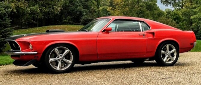
Buckeye, that is one cherry ride! You have done an outstanding job. Be proud young man.
Bob
-
A 70 prop valve? It's my understanding the 69 is separate and next to the distribution block, and the 70 is included in the distribution block.
You'll need to use the 69 tie rods.
This is my 69 distribution block and prop valve.

Bob
-
As much of a pita it is, I've only heard of connecting the lines, snugging them up real good any praying for no leaks.
Bob
-
My method of restoration is one step forward, two backwards. It's not my intention, but seems to go that way for me. Back around 2001 when I brought the car home from the body shop the first time, I noticed the stock fender opening wouldn't work for my plans. So I decided to roll the fenders which means more paint time on the fenders.
The fronts were fairly easy. With them off the car and sitting on a padded table, I used a tool designed to roll the edges inward. It bent the edge so that the tire wouldn't get cut, but was still at least an inch thick. I pounded with a soft hammer with a sand bag under it. I was able to make progress, but not as much as I wanted. I cut slits to allow the fender lip to roll under till I was happy with them. The top of the w/o is .300" thick, and the lower edges .400". I used a mig to weld the slits, and let the body shop finish the edges.
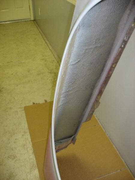
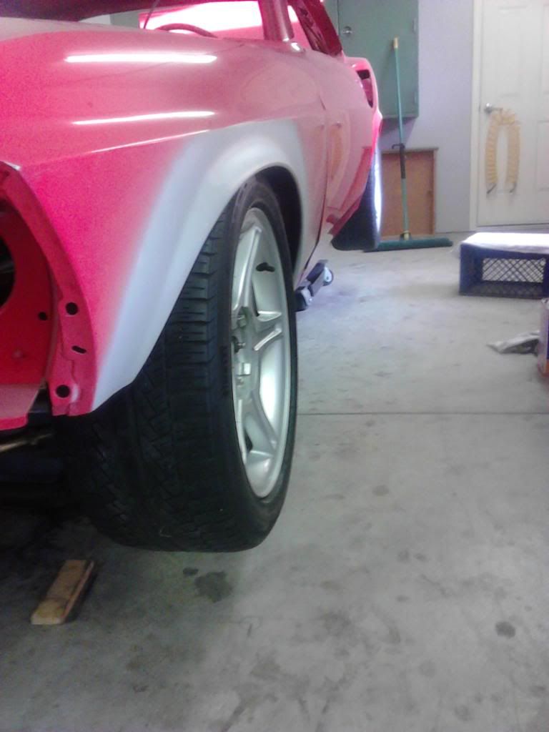
The rears were a major pita! The problem lies in the double layer of panels from the quarter panel and the wheel house panel. I did it entirely with a body hammer. Spent 2-3 hr's per side and was able to get the edge to just under 1". They have a smooth radius without any worry of cutting tires. I did not cut reliefs like the front due to the double panels.
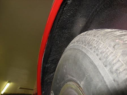
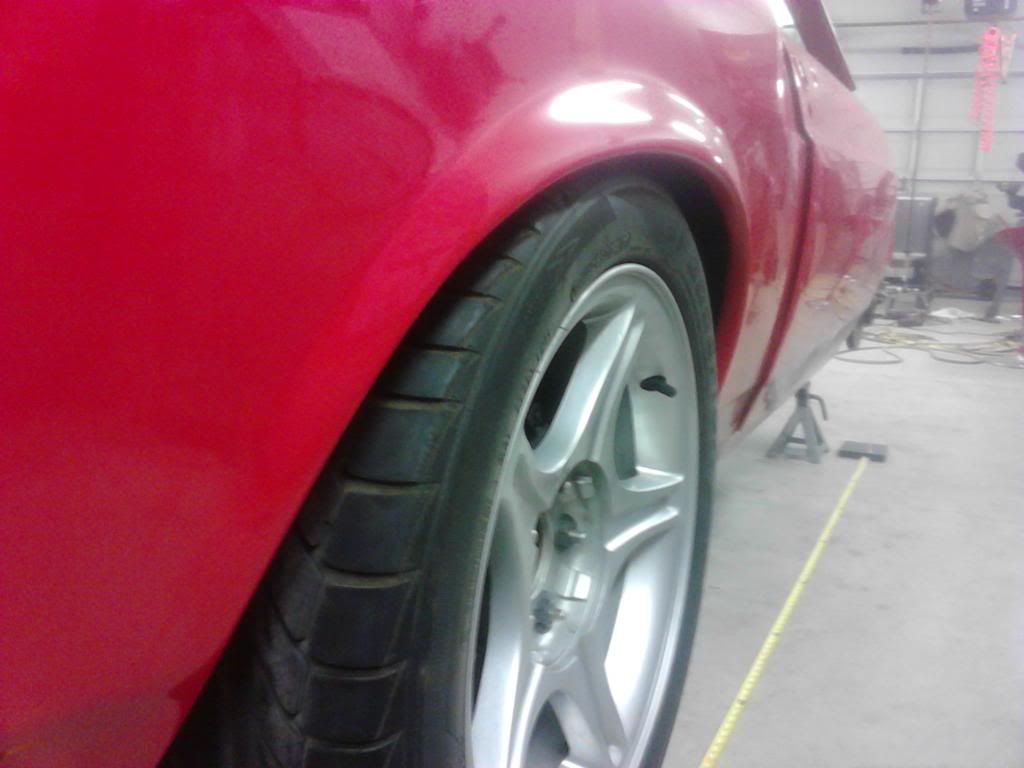
Even though it was a lot of work with a hammer resulting in sore arms and hands, I'd definitely do it again.
Bob
-
Hey first 69, where about you located? I've got a buddy who lives in Roscoe Illinois, a few miles from the border.
Bob
-
Bob,I'm surprised with all of the mods you have done that you haven't put a rack in this car. Is it in the plans? Following your thought that anything you do is better than stock, a rack is worlds better than the slop box that came with these cars.
Jim
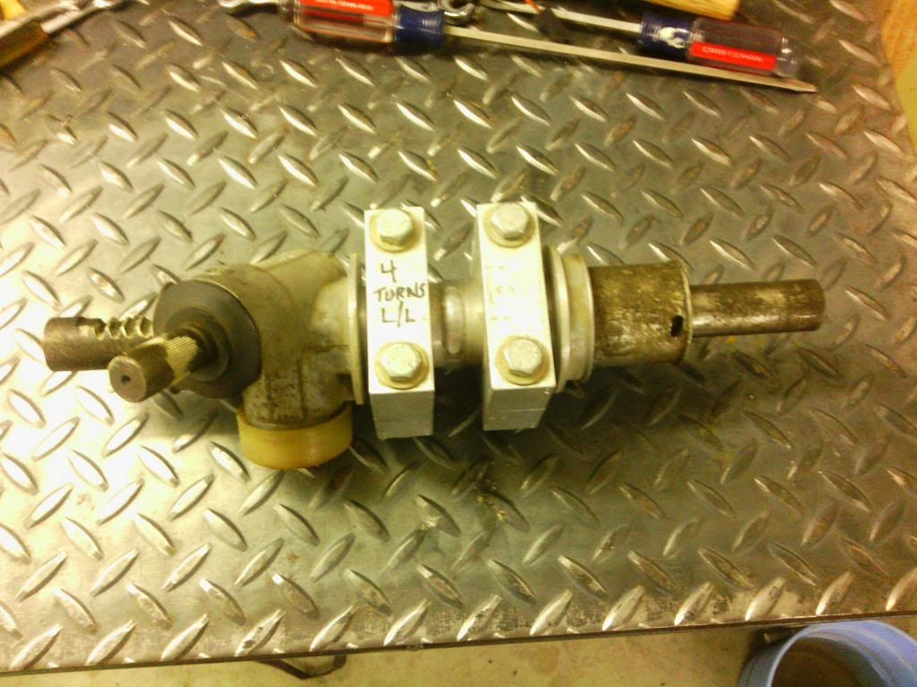
Jim Jim Jim. what person in their right mind would add rack and pinion steering to a classic Mustang? I thought of adapting a r&p back in the mid 90's. I wanted a quality unit, one I could modify myself because I'm that way, one that I could get the center tie rod pivots at around 13-1/2" (I think) to fit in line with the UCA & LCA pivot, and one with about 4 turns lock to lock like the stock Mustang box. I contacted the hot rod shop Total Cost Involved as they made a coil over front kit with rear steer. They originally used a modified Omni rack, but changed to their own design.
I bought a used Omni rack but didn't like it because of its cheap construction. I then bought a BMW alum case rear steer rack, narrowed the housing and the rack. The problem with this was by narrowing it, the steering shaft was moved to far in to the vehicle centerline and would interfere with the oil pan. I wasn't smart enough to modify it like the popular units used today are done.
I really lost interest in the conversion after it didn't work. Once I saw the current adaption method I decided that I will add the r&p after I get the car on the road. One of the first things I bought for the car was a Flaming River new box, so I'm currently not too worried about the steering. Good observation Jim.
Bob
-
Fordracing, the AFCO part #'s are:
Upper bj-20034. Lower-20036
Ball joint threaded sleeve-20043
On a related note, the tie rod adjusters that allow you to change the position of the tie rod angle fot the big bearing 70 spindle, but not the 69. They have the same hole taper but need reamed out a bit larger. The 69 has a 7/16" hole at the small end, and the 70 has a 1/2" hole. Speedway Motors sells the Ford tapper reamer.
Bob -
Thanks Fordracing. I bought the screw in ball joint cups from AFCO. No mod to the spindle hole needed. I think they are the Mopar bj, I'll look for my info.
Bob
-
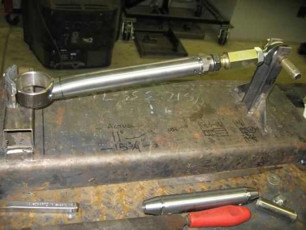
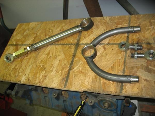
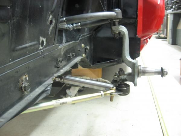
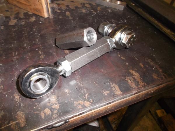
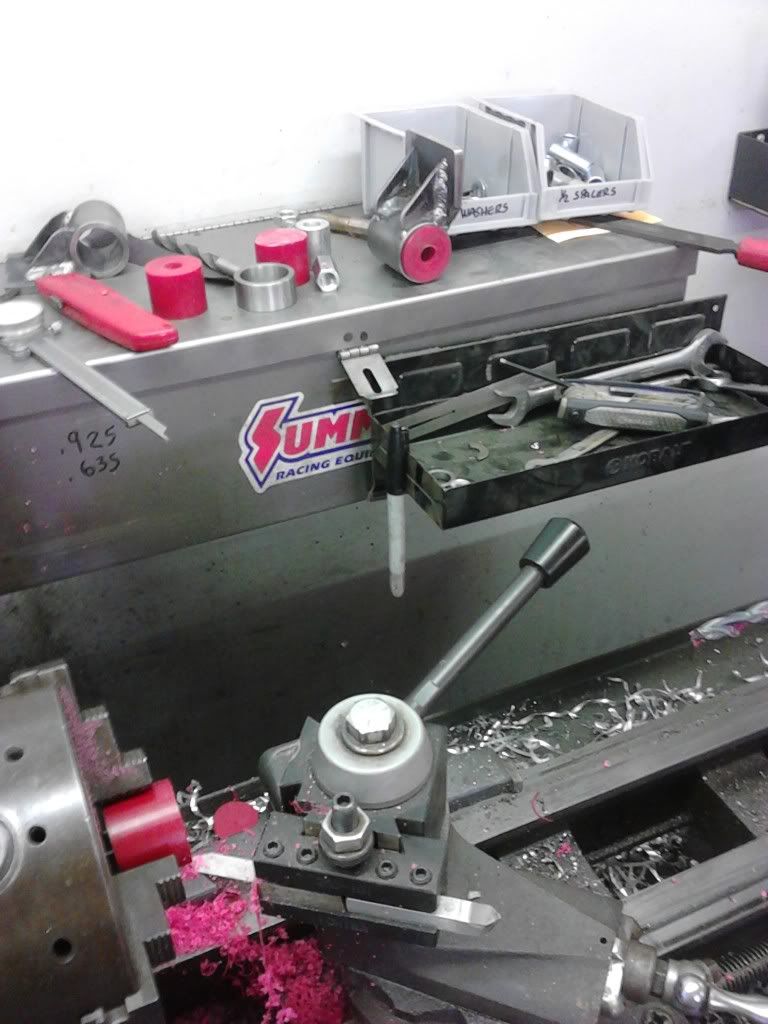
Since the front end is lowered a bit and I don't care for bump steer, I bought a tie rod adjuster from Afco. It took several adjustments to get the rod end at the correct height location. After each adjustment I moved the spindle thru its arc of travel till I found the position with the least amount of toe change.
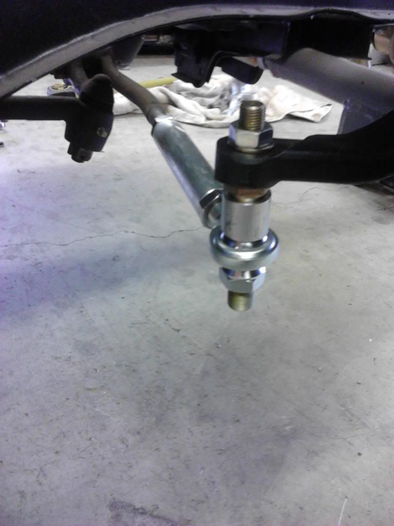
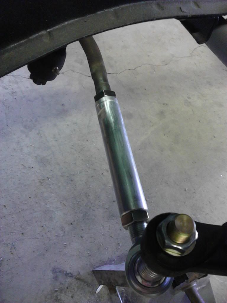
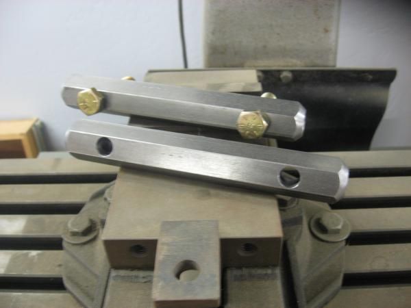
The tie rod adjuster replaced the stock outer tie rod with a shorter rod end. The stock crappy stamped steel toe adjusters were not long enough to fit the shorter rod ends. I made a pair out of 1" 6061-T6 aluminum round bar. I drilled the center to size and tapped them 11/16-18 (odd size) left and right hand. I milled flat spots for wrench adjustments.
-
Cool story. He was smarter than the average bear.
Bob
-
Couple different ways it can be done depending on the location of the damage. Anywhere probably 8-12 as a wag. Been several years since I've written a sheet. Paint time around 3. Plus materials. Somebody here surely must work at a shop with correct time.
Edit: hell, your car looks great in your album! New damage?
Bob
-
Several years ago I thought about building a chromoly tube front suspension using coil over shocks like I'd seen on many hot rods. I considered the Mustang II, but didn't really want to cut up the car. I figured by using the basic stock suspension design and pick up points (with Shelby drop), but using tubing and quality coil overs, I'd have something that rode well, looked cool and different. I knew that with my basic skills I didn't want to pay someone for something I could do as well, and for a lot less.
It didn't take to long to pick the materials and components I wanted to use. One day at the grocery store while looking thru Mustang mags I ran across a write up on the Ron Morris front coil over suspension. Holy crap, mine looked almost identical. About the only difference was he used a 1" lower control arm, and I had a 1-1/4". I felt confident mine should work out OK.
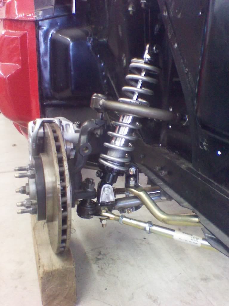
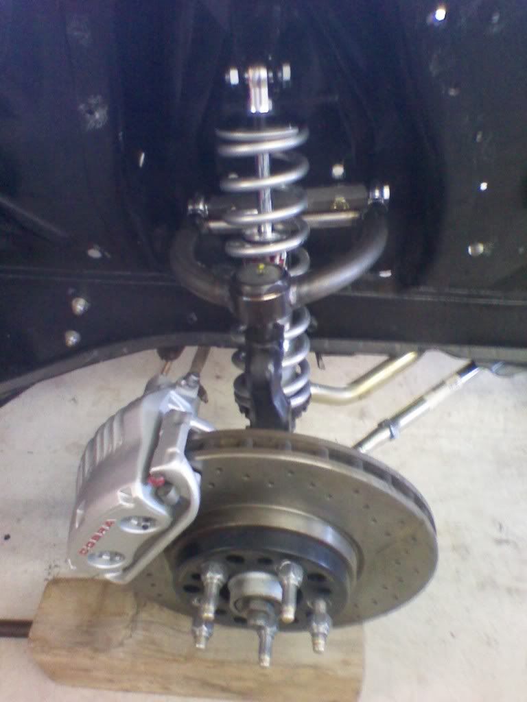
I bought the front and rear 4130 tubing from The Chassis Shop. They bent the upper 1" x .083 wall arms. I used the stock arms to build jigs to fab the tube arms. I used tube adapters to attach rod ends. The strut arms were originally 1" swedged tubes with 5/8" ends. I had a change of heart and wanted to use a 3/4" clevis. The new strut rods are 1-1/8" x .083 4130, as that is the smallest size tube I could use with 3/4" thread rod ends.

I used a piece of hex bar to make the UCA pivot shaft. Center drilled it, tapped it 1/2" -20 and tapered the ends all on the lathe.
I made the sway bar link from mild steel hex bar. I center drilled it on the lathe, then tapped them for left and right hand threads.
Front upper coil over mount.
-
Thanks waketek. My golf game and fabricating/welding and such have something in common. I know what I'm capable of, I always expect my best results, and rarely am I satisfied with the outcome. Only saving grace with this car is anything I do to it, is better than the factory did.
Bob
-
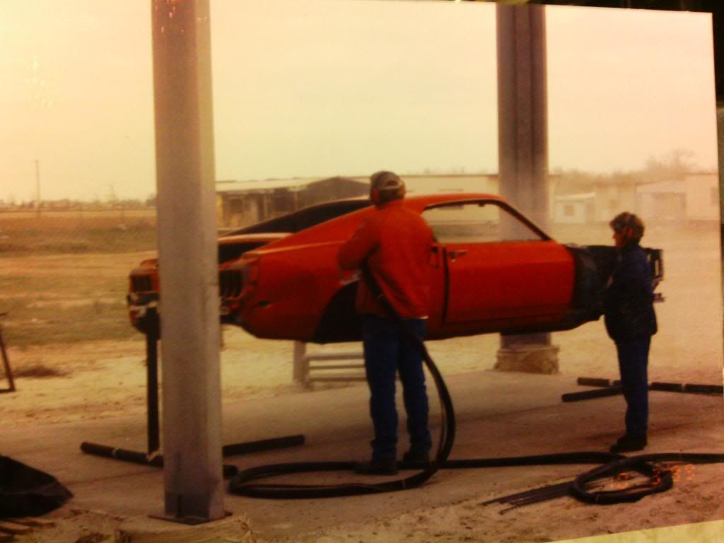
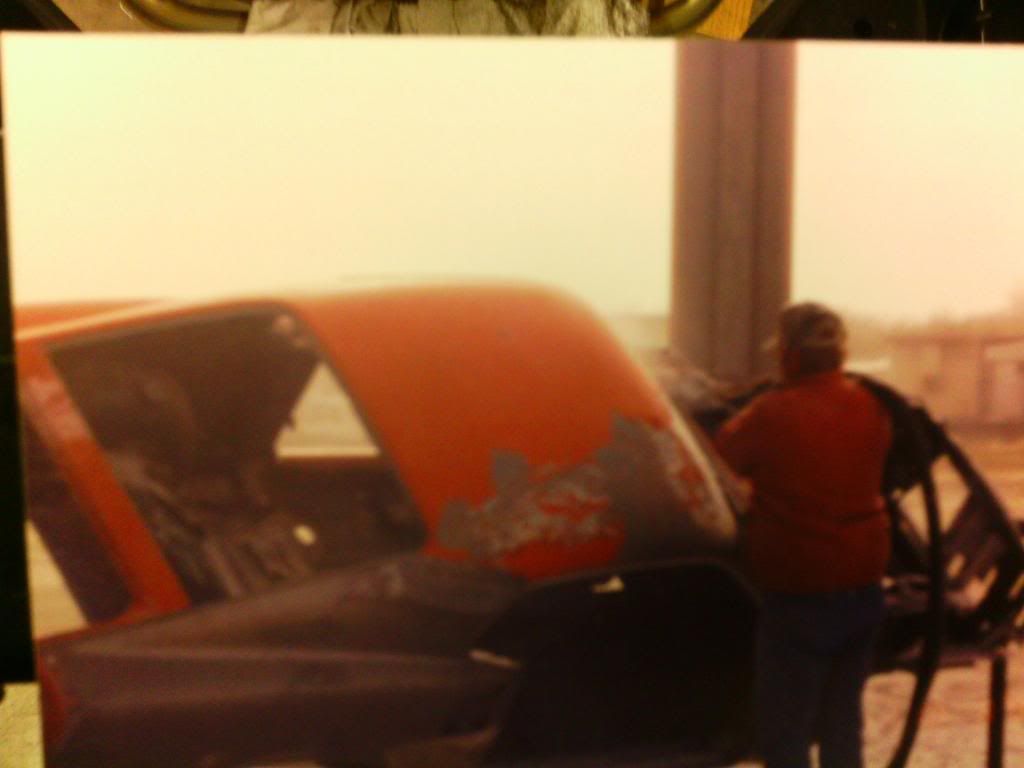
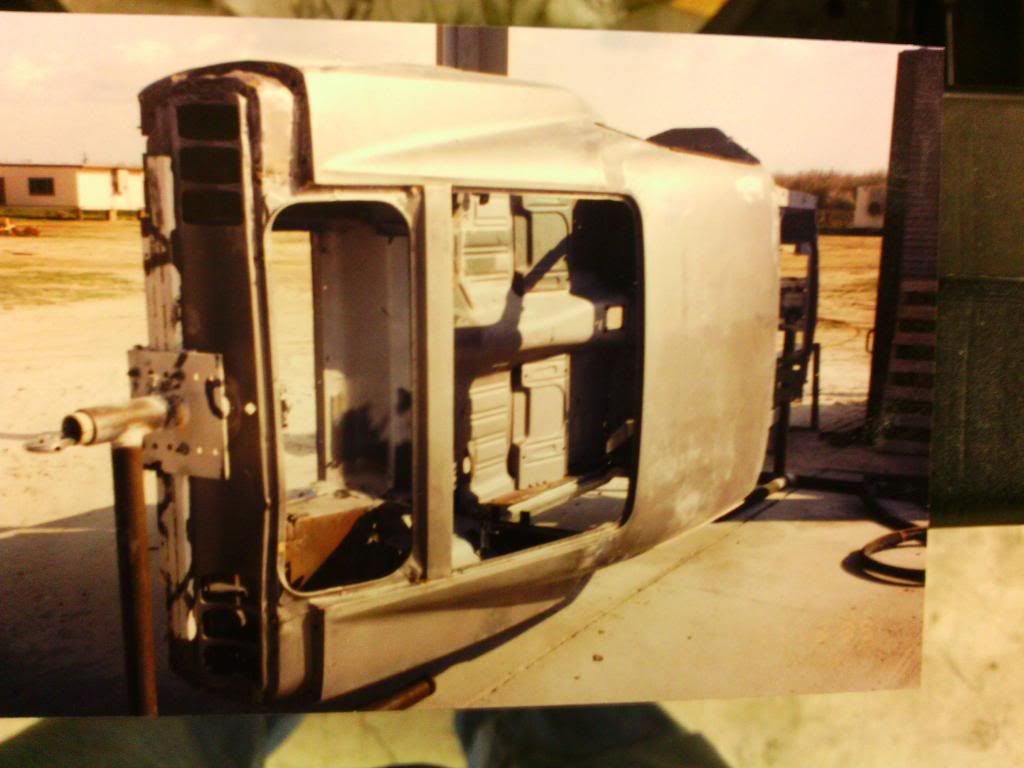
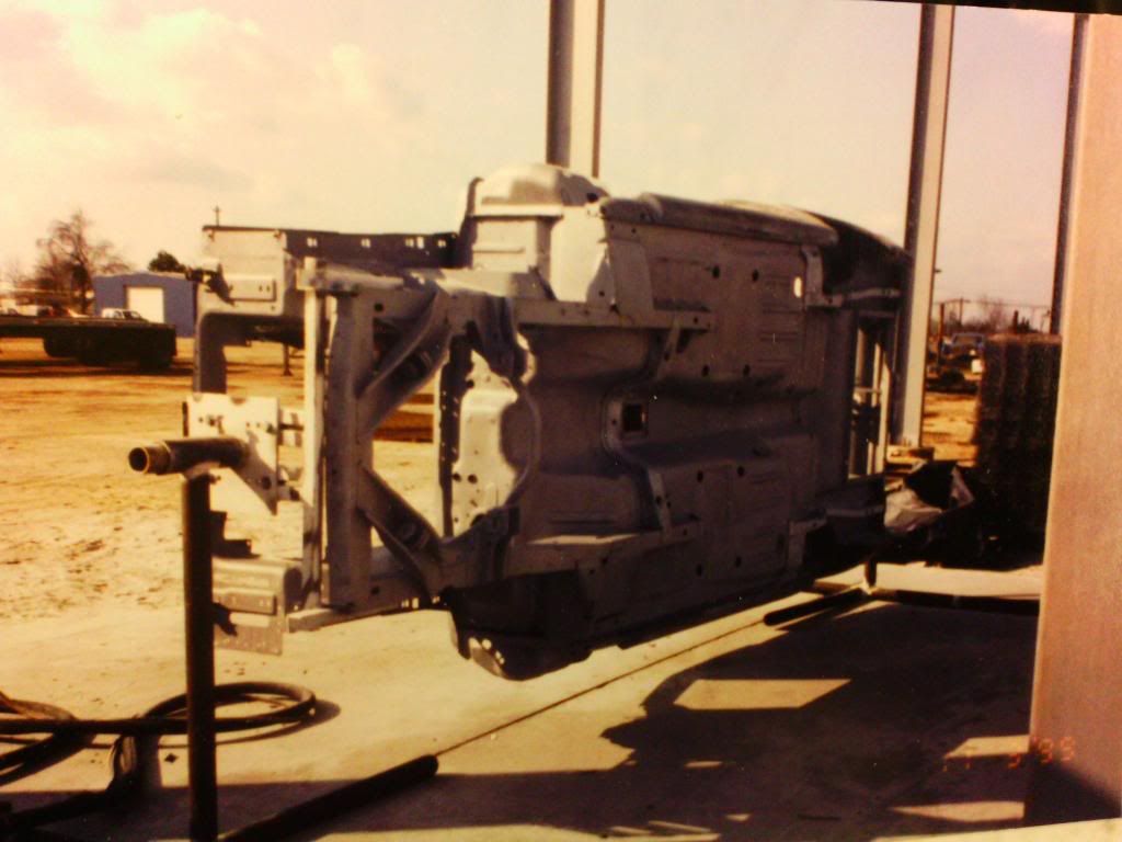
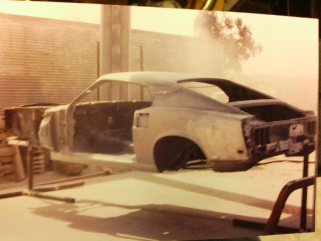
Should've started this thread with these pics, but just relocated them after many years, 5 moves and 2 divorces! Any who, back in 1998 or 99, the car was running and had about a 2 yr old paint job in Porsche India red. The trans leaked fluid bad and as I was filling it with the car running, it started hauling ass in reverse. It hit a faucet spigot with the right quarter, and pinned a concrete mixer against a gate post. Nice, didn't realize it was in reverse. But I do NOW use the parking brake!
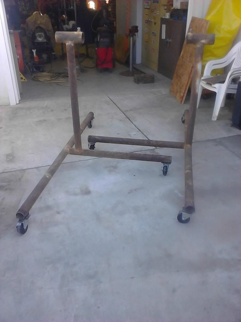
Figured with the damage, might as well do a total refurbishment. I built this rotisserie out of materials on hand, stripped the body completely and had it soda blasted. Plastic baggies are nice to label parts in, but mine sure didn't last 10-12 years.
Bob
-
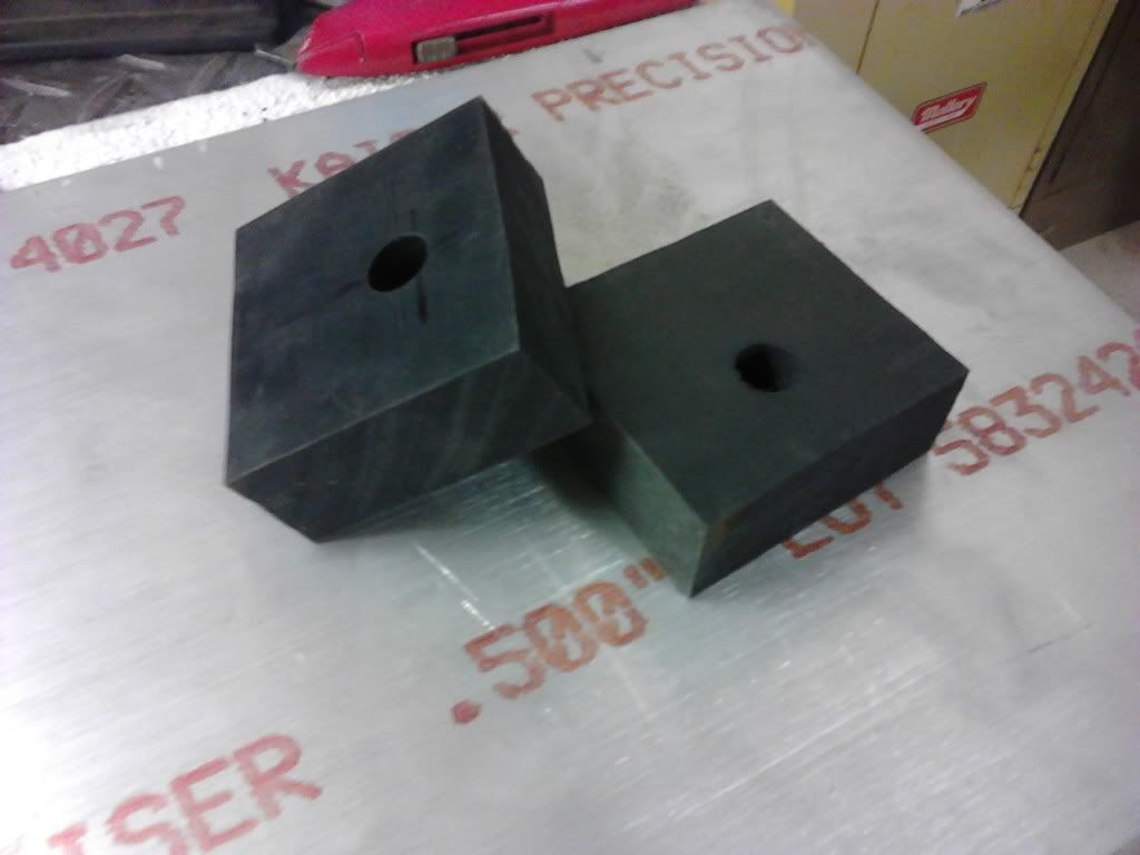
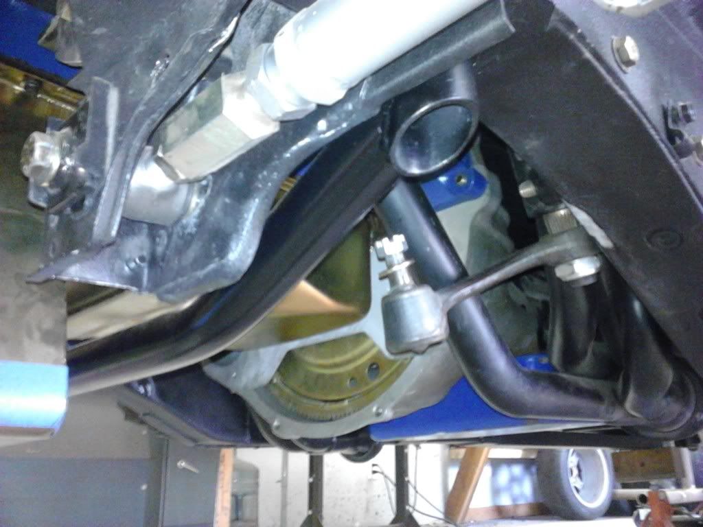
Speaking of buening's motor mount PDF file, I cut out some steel and made a set. I considered using 6061-T6 aluminum for the mounts. Seeing how I've made just about everything twice on this car, I may do it once I've got it on the road again.
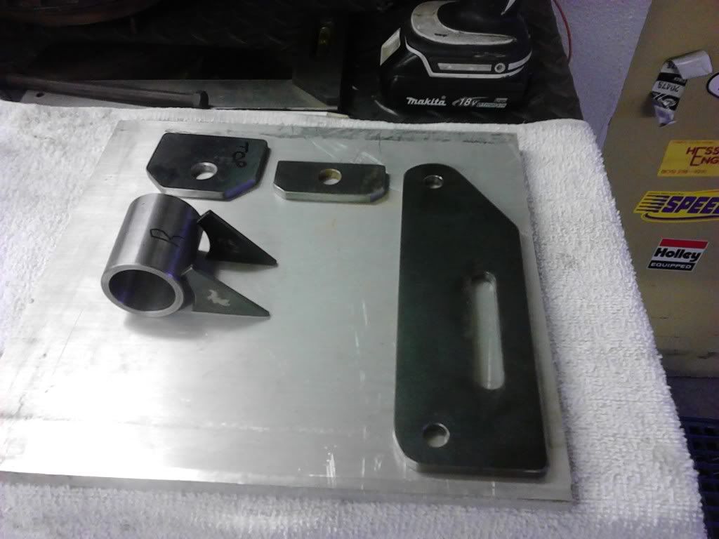
I had a piece of polyurethane rod on hand and turned it on the lathe for the bushings.

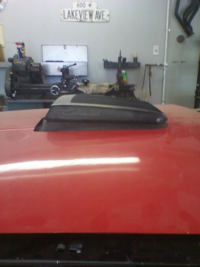
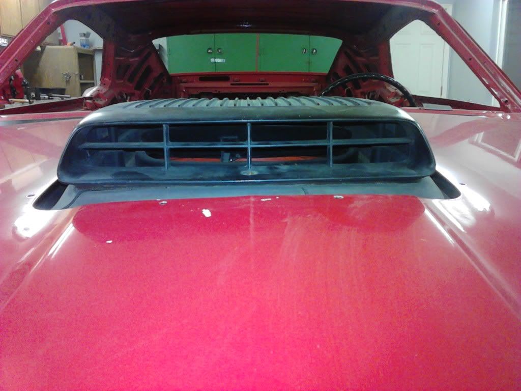
Since I was guessing on how low to drop the engine for the shaker to sit in an acceptable position thru the hood, I used a spacer between the frame mount and engine mount pieces.
I made the first spacers from aluminum, and a second set from pieces of 1/4" rubber which were glued together.
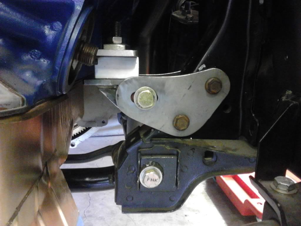
The before and after pics.

Thanks buening.
Edit: I later used a 1/4" thinner spacer and lowered the shaker for a nice fit.
-
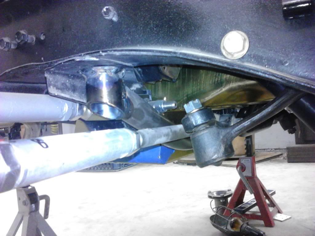
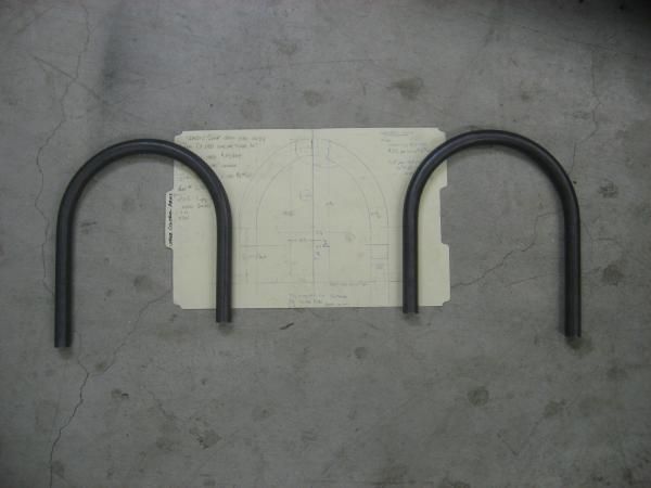
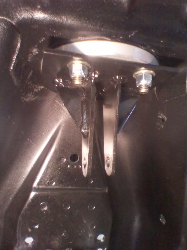
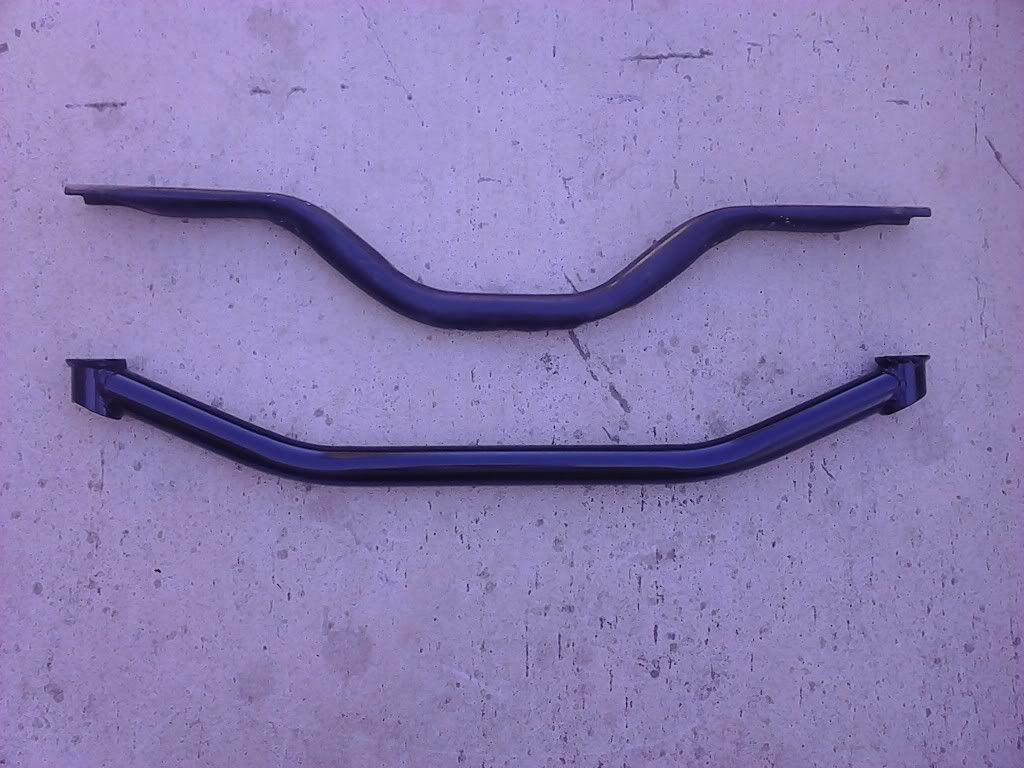
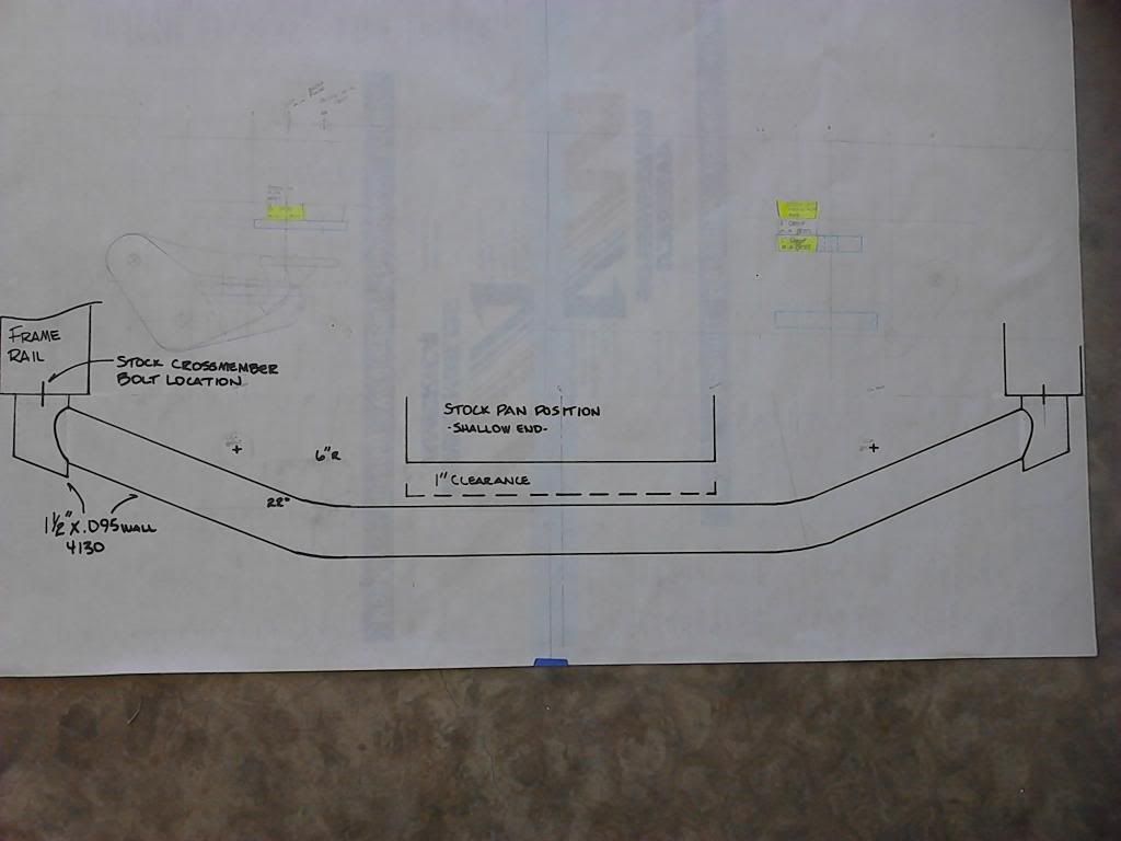
This was covered in another thread, but I thought I'd document it on my build thread. In order to lower my shaker to fit the hood, I considered milling the intake carb plate or lower the engine. Since I really liked buening's motor mount plans, I decided on lowering the engine. For my engine combo the stock front cross member design wouldn't allow the engine to be lowered. Why not make a new cross member?
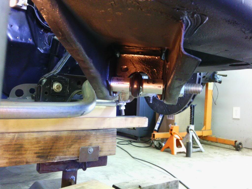
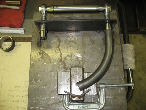
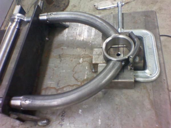
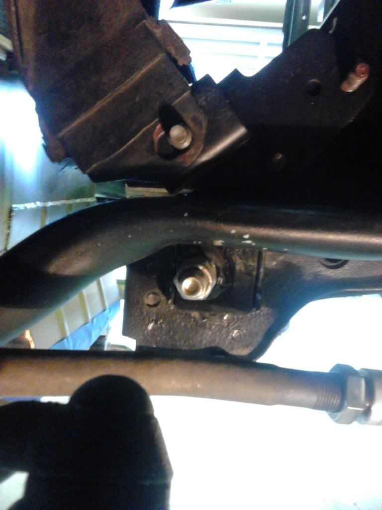
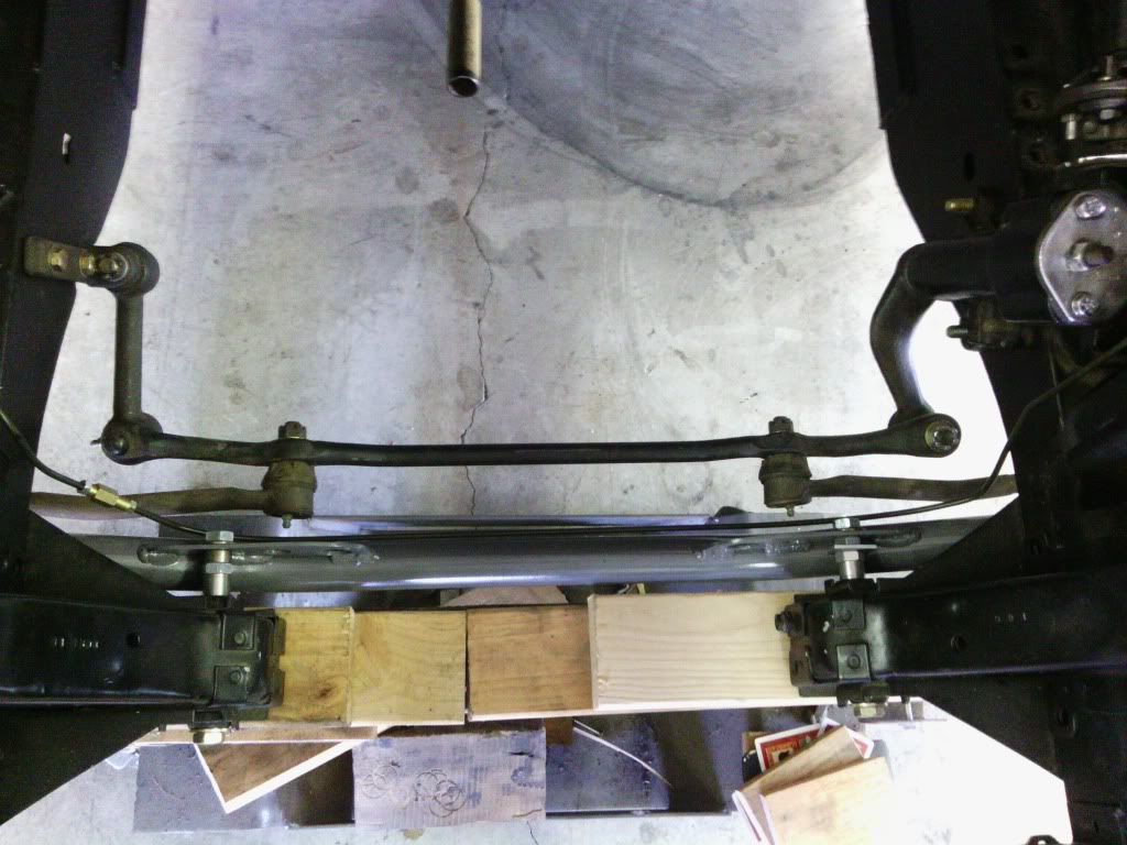
After crawling under the car and eyeballing things, I came up with a design that I thought was a good one. It would have only 2 bends as opposed to 4 for the stock, made from 1-1/2" 4130 rather than mild steel for stock, and have better looking tube mount ends vs crushed tube ends. I drew up full size plans and took them to a local race car fab shop to bend the chromoly tube. I trimmed the ends, tacked them in place while on the car, then removed them for final welding. I normalized the cross member after welding.
I had it installed for a couple of weeks before I decided to add the Shelby tie in mod to the lower control arm mounting bolt.

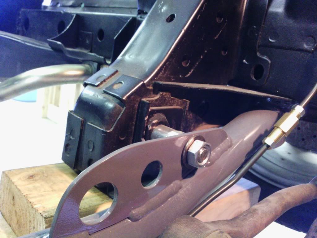
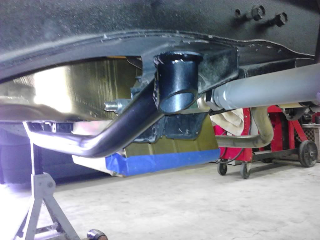
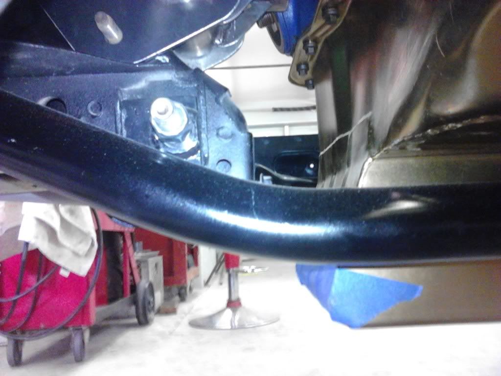
Bob


Mach 1 LS1 build
in Project Progress Forum
Posted · Report reply
Um, if you'd have used the search function you could have found where Auto Meter gauges fit just fine without any mods.
Bob