


Big Secz
-
Content Count
980 -
Joined
-
Last visited
-
Days Won
2
Posts posted by Big Secz
-
-
I went through the last two harnesses and marked off what I have and what Has been removed. Only thing removed right now is the low oil level sender.


-
Okay, so I've gone through and labeled and identified the connectors on the main harness. Circled in yellow are the connectors I still have and the ones in red are the ones I have eliminated. I verified the white connectors in my previous post were for fog lights so I got rid of them as well.

-
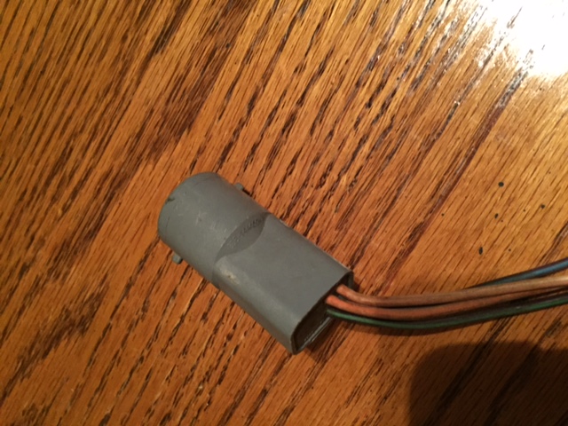
Right now I'm labeling an prepping the harness for modification. I've already gone through and cleaned and labeled most of the connectors, and came across a few connectors that I'm not sure about.
I think the green and brown connectors connect to an additional harness in the stock car. Not sure if these will be needed for the swap.
From what I've been able to find the white cylindrical connectors are for fog lights.
The round gray connector is behind the firewall grommet near the green connector.
The black connector is just past the firewall grommet.


-
I agree fordfuelinjection.com was a great reference site, did not know it had been shut down. Here are some additional ref.:
http://midnightdsigns.com/Mustang/EFI%20Swap%20-%20Wiring.htm
Thanks for the Bornco site, that is one I haven't seen yet. I did find this too which seems to be a pretty good soruce on the wiring harness modification:
http://aboutcarinfo.com/wp-content/uploads/2015/01/EFI-harness-installation-instructions.pdf
A lot of the sites out there are outdated and provide high level overviews and then reference old sites that no longer work for additional details. Trust me I wasn't asking this because I have done no research at all. Just trying to find out the best resources from those that have experience with doing this.
Since I'm in no real hurry I'm going to attempt the harness modification myself. Wost case scenario there are a ton of aftermarket harness options available. The PO gave me a second harnes that I'm not sure what it goes to. Any ideas:

-
I can source a 302 motor and AOD trans by themselves for alot less than I would pay for a donor car.
-
I know already that there is a lot of stuff out there about these conversions. But I'm going to ask some questions anyway.
Today I just scored a complete EFI setup out of a 92 Mustang. Here's the kicker....I don't even have a project car yet or a motor to put it on, but I got everything for $150 and at that price I couldn't pass it up.
So While I take my time sourcing a motor for it I'd like to go through everything clean it up and prepare it for the conversion. This includes modifying the wiring harness.
Also everything came out of a 60's Bronco, and the PO said it was running when he got it. He is switching to a carb setup. So the wiring harness may already be setup, but there are some wires that are cut and frayed. I want to be able to clean it up and make sure none of the wires I need have been cut.
Questions:
is there a way to bench test the ECU to make sure it's good?
What is the best resource with instructions on how to modify the wiring harness for the conversion?
-
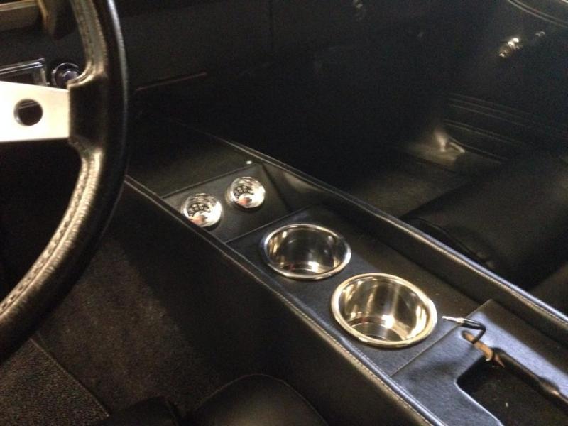
Looks good. One of my favorite projects on my Torino was the custom center console I built for it. I found I like those kinds of things more than actual mechanic work.
-
I've had two Grant wheels and hated them both, bad quality. My favorite wheel was the factory Ford OEM GT wheel that came in just about all Ford cars/trucks/vans from the late 70's to early 80's. it looks similar to the Grant wheel but more durable, is slightly smaller in diameter than the factory wheel that you have now, and you can find these wheels in the vinyl version and leather versions. The only thing that really cost is replacement horn buttons. I got a replacement horn button from CJP for more than I got the steering wheel for.
http://www.cjponyparts.com/silver-horn-button-assembly-1979-1982/p/HBG7/
I found the wheel on eBay and then took fine steel wool to the spokes to clean them up and cleaned the vinyl. Then installed it in my '71 Torino
Best is that the wheel is a direct bolt on with no modifications needed, unlike the grant wheel which requires you to take a hacksaw to the steering rod to cut off the unthreaded portion so their horn buttons don't pop off.
-
Thanks for the repliesI have aready tried a new flasher and they still don't work, and yes I have tail and brake lights, everything else works except my flashers, so could it be something with the steering wheel?
Does your horn still work? and do the blinkers work individually? If the answer is no to both questions, then its a fuse. Check the fuse block for a blown fuse.
-
To each their own. Ultimately if they have the money they can pay to get anything done they want to their cars as they should, it's their car. Regardless if the masses approve or not.
-
I've run MSD Ready-to-Run distributors in both my Mustang and Torino and loved them. Best thing is the Ready-to-Run models don't use the external MSD box, it's all internal. Super easy to hook up and never had any issues with them.
-
I've run MSD Ready-to-Run distributors in both my Mustang and Torino and loved them. Best thing is the Ready-to-Run models don't use the external MSD box, it's all internal. Super easy to hook up and never had any issues with them.
-
If you wanted to stick to a period correct Ford blue I've always been a fan of Acapulco Blue.
-
If you wanted to stick to a period correct Ford blue I've always been a fan of Acapulco Blue.
-
Printdad,
Look at it like this. You've had a black Mach 1 for 36 years, you just got comfortable with the color. Paint it back to it's original color and it will really be like having a new car all over again. If you aren't a fan of the Grabber Green then options are limitless that can really make the car a head turner. For example you could do a nice deep red/maroon color like the 2015 Mustang Ruby Red, or the Dragon's Blood red color by Ring Brothers with Black Mach1 accents or even gun metal gray Mach 1 accents.
Now is your chance to think outside of the box. Really be unique.
-
You can't use stain, it's too transparent. It will never cover the primer. You have to use paint, but there are several different techniques for getting faux wood grain. There are tools for it, some use rags, or brushes, but mostly it's done on flat surfaces. I think a brush technique would probably work best on the curved steering wheel surface.
Then there is this option too:
-
There is a lot that is involved in just being able to do this. For example you can't use just a generic sewing machine. Need to use an industrial double needle sewing machine and those are not cheap by any means. That's why I'm trying to gauge interest before delving into it.
-
Are you trying to use regular stain or are you using paint?
-
I don't have any examples, because I haven't started this yet. Still in the discovery phase. But here are a few pictures from the net that shows basically what I am talking about. I would also offer matching covers for the lower dash side panels and radio side panels.
The idea is to get the custom look via mail order and at a fraction of what it would cost if you took it to a custom upholstery shop. Of course this means in order to save some money the customer would have to install the cover themselves, which wouldn't be difficult.
-
So now that I am without a project car I have been going stir crazy with the free time that I have on my hands. I have come up with an idea and would like to get feedback from the forum on interest and to gauge a demand to see if it would be worth my time to pursue.
I am thinking about starting to make custom dash covers for Mustangs. I will create templates using an OEM dash pad. The covers would be made out of a durable vinyl/pleather material and would be stitched using French seams. French seams are the double stitching patterns that you see in modern and high end luxury cars. I would offer different thread colors as well for the customer to choose from.
The customer would keep their OEM pad and fill in any cracks and sand the surface smooth. Then I would send only the covers ready to be installed with simple installation instructions. This allows you to keep the OEM dash pad, that we all know fits much better than the aftermarket options, and get a custom upholstered look as well. This also prevents having to mail dash pads back and forth and cut down on expensive shipping charges. I would test fit each cover using the OEM pad that I would have on hand to ensure fitment before sending it out.
My price point right now would be about $250 shipped (within the lower 48). This is significantly cheaper than aftermarket pads (that are notorious for fitment issues) and not terribly expensive compared to the cheap $99 plastic cover lay options.
What are you thoughts, good, bad or indifferent?
AlexissRet reacted to this -
There is no reason why it wouldn't work. You will, however have to get one that has a built in humidistat that measures the moisture in the air and shuts off when it reaches a certain humidity. You have to have some moisture. If the air is too dry it can do just as much damage than if the air is too humid. You'll also want to get one that has a hose that you can run out of the garage, otherwise you will constantly be dumping the water out of it. I believe 45% is the ideal humidity for structures.
-
This is what has always worked for me. You have two main wires, one for switchable power source and the other is a constant power source for the radio's memory. Use the wire for the factory radio for the switchable source. The factory radio harness has a two prong connector, one side is the switchable power source and the other is for the radio light. use a test light to figure out which is correct. Then you can use a bullet connector to plug into the side for the switchable source. No splicing required.
Now for the constant power source I always run a wire to the fuse block, but you do not need to splice into anything. with the key off use your test light and touch the end of each fuse and you will find one that is a constant power source. Then use a fork style metal connector on your new wire and simply slide it into the fuse block at the fuse that is getting the constant power. Done, and no splicing into anything.
-
If you're comparing your steering to modern day cars, you're never going to be satisfied with the original Mustang PS setup. First is to note that the power steering on modern cars adjusts automatically based on driving conditions of the car. For example you mentioned that when cruising at highway speeds you have to adjust more than in modern cars. That is because at those speeds power steering assists in modern cars is reduced making the steering more responsive and tighter. Not the case in these old cars. The power steering always has a little play in it no matter what you do. You mentioned that you replaced all the PS components, you next step should be to look at ball joints, inner and outer tie rods, and idler arm bushings.

5.0 EFI Conversion Questions
in 1969-70 Technical Forum
Posted · Report reply
This is the best resource I have found so far.
http://aboutcarinfo.com/wp-content/uploads/2015/01/EFI-harness-installation-instructions.pdf
The three that I eliminated are referenced on page 3. The EGR connector that will throw a code is the EGR position sensor #13 on the fuel injector harness. They make EGR eliminator plugs that prevent from throwing the code. It looks like the only other thing that can be eliminated from the harness is the Canister Purge Solenoid #12 on the fuel injector harness and possibly the air charge temp sensor #17 on the injector harness, still trying to find out. The VSS was removed by the PO, but shouldn't need that anyway.
The the green 8 pin connector #39 and the brown 8 pin connector #31 on the main harness can be snipped leaving the wires which will be used to wire into the main wiring harness of the car.
If I wasn't planning on having AC I could get rid of all the AC related connectors. If you are going to have AC you need to keep them. There are a few other wiring mods that need to be made once it is ready to go into the car, such as the Oil Pressure and Water Temp sending units.
My next move is to re-route wiring on the main harness relocating as muchas possible to inside the car leaving only what is absolutely necessary in the engine bay to give it a clean install.