


buening
-
Content Count
2,173 -
Joined
-
Last visited
-
Days Won
12
Posts posted by buening
-
-
hey what length hydraulic hose did you end up using between the master cylinder and the hydro throwout bearing? Did it end up being too long or too short?
-
Yeah I was a bit hesitant since it looks similar to the RM mounts, but these aren't an exact copy. As shown above, I started with the stock hole dimensions and made it my own. In the end it will appear similar to RM, but not a carbon copy. Must be nice to have access to a mill and lathe! I'll probably be cutting this steel plate with a 10tpi metal blade and jigsaw :(
BTW, what thickness of steel did you end up using? I'm thinking about going with 3/8" for all plates. I have 5/16" sitting in front of me but wonder if its a bit thin. But, I guess it is what RM uses for all plates but the motor bracket IIRC.
-
So you built your own like the RM mounts to? Did you have a thread on it? Thanks for the tip. I'm installing a T56 and need to drop and move the engine back.
-
More progress on the drawings. I took a guess at the bearing sleeve length and bearing shoulder thickness. Good enough for cardboard mockup at this point

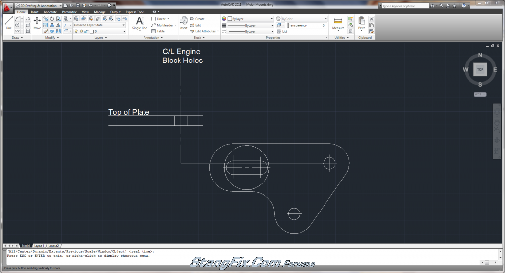
Below is the picture of the end view (as looking from the shock tower towards the side of the engine.

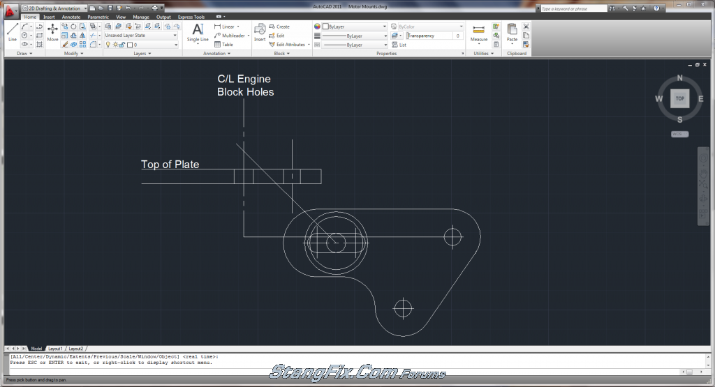
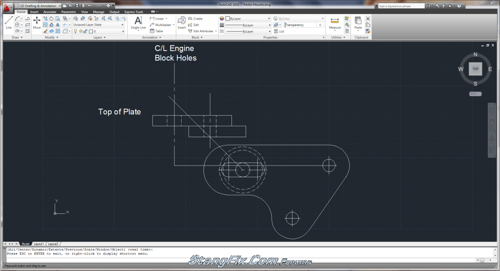
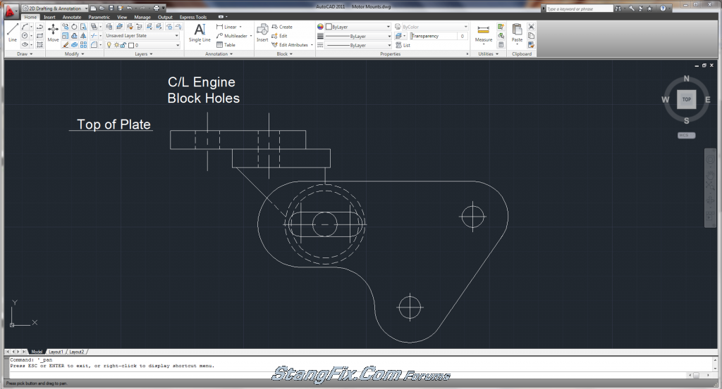
Next is to bring up construction lines to complete the top view

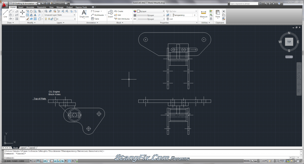
Now its just a matter of bringing all lines up and over from side view as well as end view to create the top view. I decided that I had no need to be able to move the engine forward as allowed with the RM mounts. I chose to end the slotted hole at the factory location, and bring the hole forward 1.5" that would allow me to move the engine back 1.5". A quick measurement of my shifter location with the trans in mock-up shows about an inch is needed, but I went with the extra just in case. Below is the end result with all three views finished. Nothing spectacular about them because there is a ton of lines and I got lazy making the linetypes correct for hidden lines. Next up is creating cut sheets to be transferred to cardboard tomorrow and eventually steel

-
I posted this on other forums and figured I'd stick it on here as well. I've always liked the Ron Morris motor mounts and everyone else seems to as well, but I just didn't want to fork out $225 for about $20 in steel and $20 in bushings. I also am not a fan of the urethane bushings used, so my design will utilize stock rubber bushings made for the rear shackles of our cars. The urethane bushings transmit too much vibrations to the body of the car, whereas the rubber will not. If I find that the rubber wears too quickly or the bolt pushes through the rubber, I can always buy the urethane shackle bushings to replace these rubber ones or get rubber with a higher durometer (stiffness). This may get a little wordy, but better to have too much info than not enough.
Initially I wanted to mimic the Ron Morris design but I wasn't a fan of the motor mounts being of 3 sections: the top plate, the intermediate section consisting of a top plate/angled plate/bushing housing, and the shock tower brackets. Too many sources of bolt slip or possible failure. I wanted to combine the top plate and bushing housing into one, similar to the TCP mounts but I didn't want to lose the option of sliding the engine back (which is the reason for these mounts). I decided to try to make the top plate have long slotted holes and make the front to back motor adjustments through those two bolts that go into the engine. The oil filter is in the way up front on the drivers side and there is a drain plug in the way on the front passenger side. Because of this, I conceded to try and mimic the Ron Morris mounts. My plan is to first make the motor mounts at the stock height to make sure everything lines up, and after that I will adjust my CAD drawings and will make shock tower plates that have 1/4", 1/2", 3/4", and 1" drop. The drop is needed to get the proper driveline angle for my T56 conversion, because at stock height is has 5° of driveline angle.
Here is what I have to take measurements from:


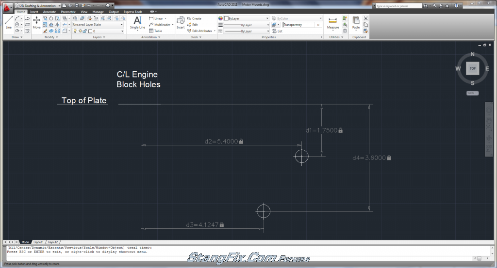
I used a caliper and plumb bob to take the measurements and below is what I came up with, drawn in Autocad:
Using these dimensions, I drew up the shock tower brackets. I used 1/2" edge distance from the edge of bolt hole to edge of plate for 7/16" bolt holes (two for shock tower) and 5/8" edge distance for 1/2" bolt holes. I wanted to keep the cutting easy, so the top edge is flat. Due to the different edge distances from the two different bolt hole sizes, the hole centerlines are not inline as seen below:

The above drawing started out with pointed corners, and then I started drawing up circles that would make the rounded edges. Below is the result:
I also put in the bushing housing and started to draw up the top plate. Below is next step completed:
I established the bolt hole locations for the intermediate plate. The long line going at an angle is 45° from the centerline of the bushing. Its just a reference point so that the angle of the plate welded to the bushing housing doesn't get greater than that angle. The next step was finalizing the intermediate plate as seen below:
The final step was to draw in the angled plate that connects the bushing housing to the intermediate top plate.
The above view is the completed side view of the motor mount assembly. Next week I plan on drawing up the top view showing the width of the bushing, bushing housing, and details of the top plate and intermediate plate. I'm waiting on my rubber shackle bushings to come in the mail. When finalized, I will break up each part so that they can be transferred to steel plate to be cut (cut plans). I plan on dimensioning everything and posting it on here so that other DIY guys can mimic my mounts...at your own risk of course
 More to come later!
 Also, when finished I'll be transferring these drawings onto cardboard for mock-up rather than going straight to cutting steel. Just in case something is off! Hope you see that this really isn't rocket science :tongue_smilie:
-
Interesting, it appears your clutch pedal has the bumper installed on it. It also appears your pedal hanger has the hole for the original bumper. You should be good to go!
-
This is true. My clutch pedal assembly off ebay came with a manual brake pedal, but I already have a power brake pedal for an automatic. You have two choices, just trim the pedal pad on the automatic or remove the pad from the manual 4spd brake pedal and weld it onto the power automatic pedal (with pad removed).
-
Hey man, I found the MustangSteve roller bearing kit on Ebay and he shows a way that we can add a bump stop to our pedal hanger. See the third picture in this Ebay link: http://cgi.ebay.com/ebaymotors/ws/eBayISAPI.dll?ViewItem&item=110334520239&viewitem=&sspagename=STRK%3AMEWAX%3AIT
FYI in case you are trying to find a way to add one! This will allow you to adjust your clutch pedal height, rather than being stuck with the stock pedal height which is slightly higher than the brake pedal. It appears it is a hood bumper that he used.
-
Have you checked the 3rd member yoke that you installed? You mentioned you swapped the 3rd members when you have the rear out of the car. There are different depth yokes and is possible the one you put in there was a bit longer than the original. This would be the first thing I check.
-
One more thing I'll add. Be aware that the pedal support for a manual trans car is different than the auto cars. See below for the comparison, and note the clutch pedal stop bumper location in which the housing bumps out more for the spot to hold the bumper whereas the auto support has a few nubs but not enough steel to drill for a pedal stop. I'm about 99% sure that a pedal stop is still needed for cars with hydraulic clutch systems, but you can verify with Modern Driveline on that.
Auto:

Manual:

-
Yeah modifying the trans tunnel support would help some. I'm going the route of not modifying the body, so motor drop mounts are the solution for me.
The shifter was just an FYI in case it has the stop bolts at the front and back of the shifter. You may take a look at it to be sure. The Pro5.0, Steeda, and others have the bolts.
Thanks for the tips on the roller bearing kit. So you didn't weld them? Sounds like a retaining clip is used, no?
I've seen the metal plate used somewhere but can't remember where I saw it. It was on the factory aluminum bell though. I'm thinking of getting a chunk of rubber, drilling holes for the lines to run through and cut a slot around the outside so that it holds itself to the bell (just like a grommet would). The steel plate would involve two plates and a bolt, and may be a little tricky to install.
-
Nope, 4.6 bell is completely different.
-
Have you messed with the driveline angle yet? I just mocked mine up with the stock motor mounts and the angle of the trans is down 5° and the rear end pinion is exactly 0° (on jack stands, not sure how I managed that). I have about 1/4" clearance from the front shifter plate bolts and the trans tunnel support. I'm definitely going to go with the lowering mounts, but I'm making my own :) I'll also slide the motor back to get a little bit more shifter clearance in the shifter opening, probably slide it back 1" or so. I'm not sure if your shifter has shift stop bolts, but if it does they are not needed. The T56 already has internal shift stops and the stop bolts of aftermarket shifters can really mess up the trans if not adjusted correctly.
Also, did you weld in the roller clutch pedal bearings or are they press in? I'd really like to avoid removing the pedal support assembly since my car has A/C and all that crap.
One other thing, have you thought about the clutch fork opening in the bellhousing with only having hydraulic lines going through? Do you know if they make a rubber grommet to fit the opening to prevent the hoses from rubbing? I assume you are using the Quicktime bell like me.
BTW, thanks for the pics of the booster and master cylinder! Hope the motor build is getting better!
-
Hoosierbuddy over on the VMF has done the 4r70w swap. A few helpful posts:
You can search by username to find more posts, but I'm sure there are others who have done this swap other than him.
-
That dead #5 cylinder caused your shaking and black smoke. If you pull a plug wire from a normal running engine it will shake pretty bad from the dead cylinder. Similar situation here.
-
That dead #5 cylinder caused your shaking and black smoke. If you pull a plug wire from a normal running engine it will shake pretty bad from the dead cylinder. Similar situation here.
-
Hydraulic is a whole nutha beast. With that you also have to make sure you limit your clutch travel so that you don't overextend the hydraulic T/O bearing, which you already know. That is the path I'm planning to take with my T56 conversion.
The reason I mentioned measuring first is just because the pedal may need lowered 1" doesn't mean it needs a 1" thicker stopper. There is a pedal ratio built in, so the stopper will be much less.
-
Press the clutch pedal down to the point that you want it to be at and measure the clearance between the stock bumper bracket and the clutch pedal arm. Just make sure you don't go through the work of drilling out the stock bumper and install the hood bumper only to find out the hood bumper is way too much ;)
-
I feel your pain. I too suffer from worn distributor gear on a rebuilt Duraspark dizzy and somewhat low oil pressure. It's about 25psi at startup and about 10psi at hot idle with a standard pressure pump and an Autometer mechanical oil pressure gauge. I too recommend getting a mechanical oil pressure gauge so you know exactly what pressures you are getting.
My motor has 4k miles on a rebuild and the cam is a Comp Cams XE262H. Main and rod bearings were checked with plastigage and everything was within specs. The oil pump was new and will be the first thing I replace if it gets any lower. Mine isn't what most would consider low, but definitely low in my opinion for a fresh motor. My situation doesn't mean your cause is the exact same though.
The distributor gear's teeth form a sharp point at the edge, rather than having a squared off edge like they are new.
SBF are notorious for lack of oil at the front of the engine. Hot Rod TV had a little trick using copper tubing and fittings to direct some of the oil directly to the front of the engine.
-
These cars didn't have the adjustable stop. There is a little rubber bumper that the silver arm touches on the portion of the hanger assembly towards the back seat. A thicker rubber bumper or a custom bumper is the only cure that I'm aware of, but you have to check your clutch adjustment so that the lower pedal doesn't cause the T/O bearing to rub.
Custom Motor Mount build
in 1969-70 Technical Forum
Posted · Report reply
Thanks for the info. 5/16" eh? Wow thats some thick stuff.
Yeah if you look at my last CAD picture I didn't make the slots as long. I have the end of the slot for the factory position and then elongated it so I could slide the motor back 1.5". You did a nice job on your fab, hopefully mine turns out half as good