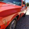
smh00n 87 Report post Posted January 5, 2023 Finally, I have enough material to put up a thread. This isn't a high end or pro rebuild, it's just me in my shed building a car I wanted by myself. Part 1 - Background. I bought this car in February 2015, after it had been imported from Texas in 2010. The man I bought it off 'rebuilt' it which is a term I'll refer to throughout this build. On the way home, stopped beside another car buyer hauling his prize home. Always wanted a Mustang, don't care too much for the earlier cars and wanted this shape. When I bought it I had nil experience of Mustangs and this was priced reasonable compared to others. However, over the course of my ownership since then I have realised if I were to buy another car again, it would be totally original and complete especially if I had no prior experience with them. The car itself is nicely specced; 302, auto, power steer, factory air and an AM stereo. It is a Dearborn build, sold into the NorthEast of US and somehow arrived in Texas. I have the Texas title here with the car. Colour is Calypso Coral with black interior, verified by the Marti report. The reason for the 69 Boss Stripes is it is a Grabber pack, which was a marketing thing at the time and gave you sports mirrors on both sides, the Boss-style stripes and a blacked out rear panel. Exciting stuff indeed. The seller had a '69 vert and his story was he bought this from the importer as an alternative to golf, so his wife would have him at home in case something happened to her (they were both retired). I wasn't fussed on the mechanical side as I can do all that, but I didn't want an body or paint. This has very little rust in it, with only the floor pans replaced. Under the dash is clean and it doesn't seem to leak. The body has been repaired in places, to an average standard. That's fine as I prefer to drive them than admire them, however the paint is not great. As the son of an 80-year old painter I am across paint and this is too dry. Who ever painted it was scared to go to the edges and they are very dry. The colour and finish is OK and after a full day on a rotary buff and some compound I got it looking a bit shinier. As soon as I bought it we embarked on a major house renovation and I was instructed not to touch the car until they were finished. So, for about 5 years the car sat in the garage. I did go out and buy a whole stack of stuff; Scat 347 kit, MSD distributor and 6AL box, Dart alloy heads, TKO600 gearbox, Modern Driveline TKO kit with a cable clutch conversion, Borgeson power steer conversion. Not smart, as all the warranty has passed and the stuff is all new in boxes until about a week ago. This shelf was my view for 5 years - all my new oarts just looking at me asking when they would be used. After 5 years I started to work on the car and get it to my liking. This post will track those changes across the past few years, up to Christmas 2022 when I went full send on it and ripped out the drivetrain for replacement. 1 TexasEd reacted to this Quote Share this post Link to post Share on other sites
smh00n 87 Report post Posted January 5, 2023 Part 2 - Brake rebuild The brakes on this car were total cr@p. They were like an on/off switch and would out you through the screen with the lightest touch. So, this was a must to fix to get the car in a state where it could be registered. It had never been registered before in Australia, but was registered when bought in Texas. The 'rebuild' had seen the brakes changed from what I think were factory manual drums front to disc (disk), using a Bendix booster and a local Australian Falcon master cylinder. The Falcon master cylinder is shorter and smaller than the OEM cylinder and is sort of a common swap here. They had also put Falcon discs and rotors on, and unknown to me at the time some strange spindle arrangement. The fix ended up being a small reaction pad missing from the internal pushrod in the booster. But before then I bought and installed all repro stuff from the US; booster, master cylinder, proportioning valve and lines. With a halfway reasonable braking setup, 3 months later the made-in-china repop booster broke. So, back to the Bendix/Falcon master cylinder. I made up all new lines as the outlets face the engine side and not the inner fender. Finally, success but I had the rear brakes locking. Much research and some poor advice from knowledgeable folks determined I needed to use an adjustable proportioning valve. Brake line set #3 was made up and I actually had brakes that worked and didn't toss me sideways. One outcome of this was the realisation a '69 booster and brake pedal had been fitted in the 'rebuild'. As they were fitted in unison, there isn't much of an issue (that I know of and can note) and the setup works. Years later when I fully registered the car, the brake balance was 75% front, 25% rear and even across both axles. Winner winner, chicken dinner. This little episode saw me visit 2 brake shops, one which I should have stayed with all the way through, and another I has dealt with in a previous profession. The second one really stuffed things up. They took out all the parts the first shop supplied, included brake shoes radius ground to perfectly match the drums, brake shoes on the rear with a good compound and new wheel cylinders. And they didn't fix the rear locking up :( As a side note, today I worked on the front calipers to find the hoses were on upside down which the second shop didn't pick up. Tools bought were a pro-style brake flaring tool and a few pipe benders. With the amount of pipes I had to modify and change, they have been well worth the few hundred dollar investment and the flares I can make are *perfect So, now the car stops, time to make some modern improvements. Quote Share this post Link to post Share on other sites
smh00n 87 Report post Posted January 5, 2023 Part 3 - MSD distributor and 6AL box installation. With the knowledge I would be a stuffing an angry little motor in, I put in the new Billet Pro distributor and the CDI box. This was more to prove the thing worked so when the new engine went in I wasn't chasing issues all over the shop. When I went on my spending spree just after buying the car, I relied on the speed shop to give me the right bits. So I ended up with a vacuum advance MSD small cap distributor, MSD 6AL box and Blaster coil along with 8mm wires. I love shiny new parts :) Whilst there, I also upgraded the start to a hi torque unit, with new wiring and a relay. Whilst my best mate is a auto electrician, I can only hope to do a pro job, but I tried. Due to the size of the 6AL, I could only put it on the passengers inner fender. Still not happy with it and would like to move it but there's no real place I can see to put it. I see MSD have now released a CDI box 50% smaller, but I can't at this point justify the $500-odd cost here to buy one. Under the box I have put a junction power box and starter relay. This takes power across the the drivers side for headlight and fan relays. I used 1 gauge wire for the starter and earth so there wasn't any issues later. The blaster coil is a big sucker, and not conducive to a neat or stealth installation. I looked at mounting it on the heads, but it is just too big. But, the motor starts and runs every time so mission accomplished. For this job I bought a pro-series ratchet crimper from Narva (a local company) and again, making connections that were solid and easy made the job so much easier. I also bought a box of the white connectors seen in the second photo, which I think is better than the yellow/red toy connectors normally seen. Luckily, no 'rebuild' items were harmed in this part. Quote Share this post Link to post Share on other sites
smh00n 87 Report post Posted January 5, 2023 4 - Holley Sniper install. This was a Big One. I had originally bought a AFM 650 double pumper carb, but as I wanted a reliable, hassle free low maintenance car, I started looking at TBI. Holley and FAST were the gun things 5 years ago, and both of them were copping static on forums. I decided on the Sniper as it integrated with the MSD ignition, and Holley had supplied Fomoco from day one, so I thought as a die hard Ford fan I ought to stay with family. I bought the base 600Hp, 4 injector kit and then bought the matching Holley EFI fuel tank with the sender and fuel pump inside. I also bought a stack of AN fittings, filters, fuel hose and hard line and associated clamps/brackets etc. To make my job easier I also bought an EFI clamp kit (the type with the 2 'ears' that get squashed down). As the motor in the car when bought was a '74 302 with a cast iron 2bbl intake and 2bbl carb, I bought for cheaps a Edelbrock Torker manifold. First off, I fitted the fuel tank. This was actually a Tanks Inc. unit that was supplied in a Holley box. In the 'rebuild' a large selection of what we call tek screws were used in the car. Dash, trim, fuel tanks, you name it they were there. The tank had a selection of fasteners holding it in. What I don't like about this tank, is the top load of the sender and pump. When I did this the in-tank sender and pump Holley now have wasn't available, so I have this all sticking up prone to damage. I tried making sugar out of shiite but still not happy with it. The centre fitting is a vent and I have made a hard line going back to the centre support, looping and venting outside. The EFI clamps are visible in this shot. One issue with the sender, if you cannot use AN fittings into the sender. This is a -8 to match the hose I had bought - I bought all -8 fittings for the entire supply and return system - but -8 don't fit. D'Oh! So, I had to buy all -6 lines, fittings and tube. Moving along, I wanted a clean install so made up a bracket under the tank. This is a 10 micron filter, but since then I have added a 40 micron filter and run them in sync. I then ran alloy/steel tubing front to rear, up inside the transmission tunnel. In the engine bay I have terminated them just at the vertical and crimped hose on. I used Gates EFI hose all through, designed to accept Ethanol although I won't be using Ethanol in this car. The wiring, as previously mentioned has all been done with solid connectors, avoiding interference issues and tied off. I've never had an issue with the system. Now I have EFI, I can plug it into the MSD system for a wholesome, happy engine. As the distributor timing is managed by the Sniper ECU, first thing was to loose the vacuum advance. Instructions make it sound easy but there is a bit of work. Luckily, MSD give you all the bits needed to lock out the advance, which is probably a dollar cost but 100 dollars value to the customer. First, remove the fandangled vacuum advance unit. If my memory is right, this photo shows an issue with removing the module from the distributor slot This wasn't a 5 minute job, and on a $600 distributor you don't want to be reefing stuff out with a plumbers wrench. Next, pull the weights out, fit the including locks, put it all back together and breathe. Once done, go into the handheld screen, set your CID, cam type and save and start. Whilst you set the idle at the carb as per normal, you can also set it electronically. Once you save it, it is instant. This was a good few days work, but I was in no hurry. First start it fired and idled without issue. The system shows the learn progress as you drive and I think it is getting better, but honestly with a tired old 302 I wasn't interested in 1/4 miles or land speed records. The system has much more capability than I have, and you can change the fuel tables, it can handle nitrous, so has a lot of features. For me, I am just happy it has been solid for the past 3 years. The only thing I don't like is the cycle time of the ECU when you first start it. It's about 3-4 seconds but seems longer. If you are going to hit a bank in your EFI-installed Mustang, my advice is leave the motor running. The fuel pump is also slightly noisy. It can be a bit of wank factor or an annoyance. Mr, I'm used to it and it doesn't worry me no more. Quote Share this post Link to post Share on other sites
smh00n 87 Report post Posted January 5, 2023 Part 5 - Doof Doof a.k.a. new stereo. I like my music and I like it loud and clear. So I started looking at my options, and came down to Rockford Fosgate or Alpine. Kicker wasn't a consideration as my wife bought a car with a full install and unless you were running it hard and loud it lacked depth and warmth. I go past a audio store on my way to work, so one day I poked my nose in. The man talked me out of Rockford Fosgate based on my parameters - not to rattle windows a block away but to give a good, fat clean sound. He recommended Hertz. I know of them as I had rented cars from them, but he set me straight. So, some time later I walked out with a 4 channel 500W amp, a 12" 500W sub, 2 6x9 3 ways and 2 x 4 inch 2 ways, along with cables and junk. Before I got to put it in, I found a cheap, new 5 channel Hertz amp so bought that. Wanting to keep it looking stock, I bought another repop radio bezel and proceeded to chop it up. I can't find the pics, but I cut it wider than original, glued up a box from plastic, cut the radio opening up and glued it all together. I don't have a close up but this is it now: The 6x9 I cut the original parcel shelf out a bit to fit them in, then cut a hole in the parcel board to put the sub into the centre. I trimmed the hole with some rubber extrusion. I was going to put fabric across it to hid it, but the porn star in me came out and I left it there in view. The sub is in a box which they tell me makes it better but I have no idea if it does or not. The front speakers I changed to a set of 4"x6" 2 way, with a bit more power. I'm old skool and used to having the big speakers in the back, but the current trend is to have the sound coming 'front of stage'. Not wanting to chop either the door frames or the trim up to fit bigger speakers I settled on these. With 80W max, they kick the repops butt both in sounds and size. I ran all the wiring from the head unit up the drivers sill and the power down the passenger. The amp I made a wooden board to fit on the floor on the transition panel. This was to make it easy to access and to keep it out of the way The box hanging down is the sub enclosure. I mounted it with rivnuts and button head set screws form the top. This is an example of our cheap wire shield. I normally use Summit stuff, which is excellent and doesn't fray, but tried this junk as it was cheap. Now the system is in, I am a convert. The sound is clear, does not distort and have plenty of bass. Being able to control the sub level really helps, as early music does not have a bass-enhanced sound, where todays music is heavy on the bass and it is all you can hear. If anything, it is too loud in the car at levels over 18 on the head unit, but outside the car it is like a rock concert. Very handy when working on the car. So, if you want an alternative, need 6x4 or 4x6 speakers with good sound, the DXC460.3 are my hot tip. Quote Share this post Link to post Share on other sites
aslanefe 333 Report post Posted January 6, 2023 On 1/5/2023 at 3:40 AM, smh00n said: 4 - Holley Sniper install. This was a Big One. I had originally bought a AFM 650 double pumper carb, but as I wanted a reliable, hassle free low maintenance car, I started looking at TBI. Holley and FAST were the gun things 5 years ago, and both of them were copping static on forums. I decided on the Sniper as it integrated with the MSD ignition, and Holley had supplied Fomoco from day one, so I thought as a die hard Ford fan I ought to stay with family. I bought the base 600Hp, 4 injector kit and then bought the matching Holley EFI fuel tank with the sender and fuel pump inside. I also bought a stack of AN fittings, filters, fuel hose and hard line and associated clamps/brackets etc. To make my job easier I also bought an EFI clamp kit (the type with the 2 'ears' that get squashed down). As the motor in the car when bought was a '74 302 with a cast iron 2bbl intake and 2bbl carb, I bought for cheaps a Edelbrock Torker manifold. First off, I fitted the fuel tank. This was actually a Tanks Inc. unit that was supplied in a Holley box. In the 'rebuild' a large selection of what we call tek screws were used in the car. Dash, trim, fuel tanks, you name it they were there. The tank had a selection of fasteners holding it in. What I don't like about this tank, is the top load of the sender and pump. When I did this the in-tank sender and pump Holley now have wasn't available, so I have this all sticking up prone to damage. I tried making sugar out of shiite but still not happy with it. The centre fitting is a vent and I have made a hard line going back to the centre support, looping and venting outside. The EFI clamps are visible in this shot. One issue with the sender, if you cannot use AN fittings into the sender. This is a -8 to match the hose I had bought - I bought all -8 fittings for the entire supply and return system - but -8 don't fit. D'Oh! So, I had to buy all -6 lines, fittings and tube. Moving along, I wanted a clean install so made up a bracket under the tank. This is a 10 micron filter, but since then I have added a 40 micron filter and run them in sync. I then ran alloy/steel tubing front to rear, up inside the transmission tunnel. In the engine bay I have terminated them just at the vertical and crimped hose on. I used Gates EFI hose all through, designed to accept Ethanol although I won't be using Ethanol in this car. The wiring, as previously mentioned has all been done with solid connectors, avoiding interference issues and tied off. I've never had an issue with the system. Now I have EFI, I can plug it into the MSD system for a wholesome, happy engine. As the distributor timing is managed by the Sniper ECU, first thing was to loose the vacuum advance. Instructions make it sound easy but there is a bit of work. Luckily, MSD give you all the bits needed to lock out the advance, which is probably a dollar cost but 100 dollars value to the customer. First, remove the fandangled vacuum advance unit. If my memory is right, this photo shows an issue with removing the module from the distributor slot This wasn't a 5 minute job, and on a $600 distributor you don't want to be reefing stuff out with a plumbers wrench. Next, pull the weights out, fit the including locks, put it all back together and breathe. Once done, go into the handheld screen, set your CID, cam type and save and start. Whilst you set the idle at the carb as per normal, you can also set it electronically. Once you save it, it is instant. This was a good few days work, but I was in no hurry. First start it fired and idled without issue. The system shows the learn progress as you drive and I think it is getting better, but honestly with a tired old 302 I wasn't interested in 1/4 miles or land speed records. The system has much more capability than I have, and you can change the fuel tables, it can handle nitrous, so has a lot of features. For me, I am just happy it has been solid for the past 3 years. The only thing I don't like is the cycle time of the ECU when you first start it. It's about 3-4 seconds but seems longer. If you are going to hit a bank in your EFI-installed Mustang, my advice is leave the motor running. The fuel pump is also slightly noisy. It can be a bit of wank factor or an annoyance. Mr, I'm used to it and it doesn't worry me no more. I have the Holley 12-305 fuel tank module (used on a regular gas tank) and it is a little noisy too especially when the fuel level is at or below quarter. Changing the pump on the Holley module to a genuine Walbro might solve the problem. It takes Sniper a few seconds to prime the fuel line and inject the prime shot before start. I usually turn the key to on, start buckling up and by the time seat belt is on, prime shot is done. If you do not wait for the prime shot, it takes longer cranking to start. Couple years ago I modified/locked a Ford duraspark dizzy to have Sniper control the timing. Couldn't get it to work and put that project up. Need to play with it some more some time as I have seen posts where people got Sniper to control timing using a duraspark dizzy which has the same magnetic pickup as MSD dizzy. I am running 2 bbl Sniper. How is the cold start on a cold day for your install? My hot idle is set to 550 rpm and cold idle is set to 850rpm, Sniper can't get it to 850 as IAC hits 100% around 700-750 rpm when it is cold.; it still drives fine without stalling though. Can start it, then put it in gear and go without waiting for the engine to warm up. Have been trying to get the cold day start rpms adjusted for a couple years now; trying to get it to start a little high, then slowly drop down like modern vehicles in cold weather. Quote Share this post Link to post Share on other sites
smh00n 87 Report post Posted January 6, 2023 Not sure what a Pro Billet costs over there but I had mine in, running and sync'd in about 10 minutes. To me that's worth a lot of money in saved hassles. We don't have 'cold' days here. Probably 5 degrees C is the worst. It's also parked in a garage. The cold starts (and hot starts) are effortless; turn the key, it boots up and idles clean straight away. It may have a short period of higher idle but not as noticeable as our new cars when cold; not enough to notice it. The cold driveaway is the best part. We have a reasonably steep driveway and it goes up without hesitation. Across the valley from us someone has an old Falcon V8. He has to sit there warming it up, then coughs and farts all the way up the road for a bit. Man, I do not miss that hassle at all. Idle I had set about 900 as it was an auto which dropped to about 750 in drive. Quote Share this post Link to post Share on other sites
aslanefe 333 Report post Posted January 7, 2023 1 hour ago, smh00n said: Idle I had set about 900 as it was an auto which dropped to about 750 in drive. Mine is auto also, C4 with standard torque converter. My idle stays the same both in park and drive. Quote Share this post Link to post Share on other sites
smh00n 87 Report post Posted January 7, 2023 Part 6 - a squeaky balljoint that got worse and worse Now I had this bad boy stopping and sounding good I started driving it around, just locally to the shops and stuff. Amazing how many people like old Mustangs, with waves, toots and people stopping to look. But when you drive them, things wear and it started to develop a squeak in the front LH ball joint. No problems I thinks, an afternoon job and all fixed. Wrong. One thing lead to another and suddenly I had a Mustang front suspension strewn across the floor. Why? Well, the 'rebuild' obviously didn't go too well as Old Mate had put 2 different sized uprights in the thing: What in the earth makes someone do that? At least they got it straight and square with multiple washers on the top wishbone bolts. Further carnage -" just throw the bushes in and tighten the feck out of the nuts will ya". Luckily, we have Falcons here which were built up to 1990 that were basically the same suspension as Mustangs. The last of them, the XF series, had strengthened top wish bones and rubber bushes rather than the old nut style pivot. And as luck would have it 10 miles down the road I have a bloke who has a heap of old Falcons in a field, including an XF. So, $250 later I had the entire front suspension including the alloy brake calipers in the back of my ute. A session on ebay had new poly bushes, balljoints, bearings, seals, paint. I also bought some local lowered springs and a 1 1/8" sway bar. Sandblasting, painting and wire brushing and I had something looking a bit nicer. I also replaced all the tie rod ends with new ones bought for the Borgeson conversion sitting on the shelf. The brake calipers used were XB Falcon, of around 1972 vintage. I didn't change these at this point as I was unsure how I was going to go. Legally, changing the brakes meant I needed an engineers report and a full brake test. Such is the idiocy of our road rules, I cannot put later, better performing brake calipers with better compound choice on the car but I can stuff a 429 in it and not touch anything. We have locally made camber bolts made here which are stronger than the Ford ones, so they went in as well. The sway bar was fantastic - it fitted exactly and I didn't need to anything to fight it in. This was made by Signature Sway bars, which is run by the son of Selby suspensions, quite a famous name in aftermarket suspension down here. One it was all put back together, I thought it handled much better. Certainly the front didn't 'wash out' with understeer like it did before, but maybe that was because it was so out of alignment. 2 RPM and Mach1 Driver reacted to this Quote Share this post Link to post Share on other sites
smh00n 87 Report post Posted January 7, 2023 Part 7 - This is not cool Now, with a driving, stopping, steering, reliable car I started to use it more. But then summer came along and we had issues. The thing started to boil in traffic, so I bought 2 fans off ebay and dropped them in. Some relays, decent power from the battery and I thought I had it done. But no, the car that keeps giving had more. Still boiled. So, I bought a cheap alloy radiator off ebay. For 180 bucks I thought if it went all bad it wasn't a big deal These are BIG, as big as a big block car and 4 core. Not very large tubes but what do you want for 180 bucks? They are supplied with 'pusher' fans. So, fans, big radiator and summer. All good? Nup, still boiled. So, blame the fans. Buy new 2,000 CFM fans from a reputable shop and stick them on. They tell me pushers are no good and you need pullers. Take my $350 then and send them up. We got along alright for a while, then it blew a head gasket. Worse, it started spitting the fan belt off. The result of many hours of testing, thinking, testing, checking identified that the lower radiator was collapsing, as a result of so much crud, scale and junk in the block that it had filled the radiator with junk. They are sneaky these things, they stay fat and puffy at idle but squash in with some revs - and I didn't pick it up till later. After looking at what the issues were, I also found out that the engine had early ('69 and earlier) pulleys, alternator and power steering brackets, with a 1970-on drivers side water pump. Now, if you are not aware, the LH outlet pumps are longer than the early cars and they are not compatible. It still shits me to this day to see pulleys and brackets advertised by the Mustang suppliers as '1964-1973' fitment. I should have picked this up when I replaced the alternator earlier on, but I think at the time I just decided as I was replacing the engine anyway, I'd fix all the issues that were present. With some help from a man in Melbourne, I had the correct crank and water pump pulley and the matching alternator brackets. The power steer pump was still suspect but I had the Borgeson conversion to do, so I just made up a spacer to suit. This then posed a new issue - the 347 kit I bought had been supplied with a 3-bolt balancer and worse, the rotating assembly had been balanced by now. What to do. I bought a new 4-bolt balancer and test fitted all the bits to confirm alignment. I was intending to flush the radiator and put it all back together, but all the radiator shops laughed at me and told me to walk when I told them it was an ebay special. So I made the executive decision to give up on the current, leaking, bog standard auto drive train and actually start rebuilding this thing. I have to say, the ebay radiator actually did work - it cooled the thing down from around 210 to 185 when both good fans were on and could keep it at a steady temperature when cruising. So I bought another, simply because I knew it worked, and 180 bucks was cheaper than the 200+ being charged for a flush (if I could find someone who could stop laughin when I said 'ebay alloy radiator' For reference the radiator is a GPI one, now sold by many vendors on ebay. 2 RPM and Mach1 Driver reacted to this Quote Share this post Link to post Share on other sites
smh00n 87 Report post Posted January 7, 2023 Part 8 - Engine machining and prep Prior to the Cooling Incident, I had started the engine build. I had bought a 302 roller long block from a guy, who assured me it was standard. Well, pull the heads off 6 months later and its 0.030". And has a lip. Dammit. Roller blocks are not common here, Falcons were not fitted with Windsor's since 1969 when Ford changed over the the Cleveland, which ran until they stopped making V8 Falcons in 1983(?). They only started being fitted to Falcons in 1993 and were the injected version. As such, they command a lot of money ( I really need to do a road trip buying every 351 roller in the US and ship them here) and I ended up paying $400 for a bare, standard block that had been in a corner for years, supposedly from the US which the 'expert' selling it claimed were a better casting than the Australian-supplied ones. So, off to the machine shop with my now 5-year old brand new bits. Let the fun begin. My engine combo consisted of Scat cast crank, Scat H Beam steel rods, SRS forged 0.030" slugs with -5cc domes, Dart Pro 1 heads with 58cc chambers, 2.02/1.60 valves, Lunati cam 20350711 (221/229 @ .050, .549/.565 lift on a 112 LSA), steel flywheel, ARP studs for mains and heads, HV oil pump and a windage tray. I also added a RPM airgap manifold and JBA shorty headers. Originally it was just drill the holes, balance, clearance and check the valve springs. But even though I wasn't chasing power on it, I elected to go with a mild port and polish on the heads. Unknown to me, I had bought rods with a Chev (uuurgh) main journal, so the crank needed to be ground to suit which was cheaper than new rods. And when I went to pick it up and pay for it, the man claimed they had used 3 slugs of Mallory and it would be another few hundred, thanks. Well, fast forward a bit and the crank has not got any Mallory in it. No more work from me for that shop. They seem to have done a good job, the bearing clearances are nice, the ports are a bit nicer and they didn't loose anything and gave me my wrong bearings back. And that brings me to today. 1 RPM reacted to this Quote Share this post Link to post Share on other sites
smh00n 87 Report post Posted January 7, 2023 Part 9 - a 347 build Having decided to not re-fit the radiator I started on the engine. A family death also spurred me on, not thinking about it and doing it. First thing was to rectify the balancer issue. Luckily, I made contact some years back with a historic Mini racer, who happens to build some of the fastest engines in the category. He put me on to a machinist who worked from home, and was part of the early performance industry here. He now balances engines mainly for racing and is old school trained. All he wanted was the crank, a rod and piston and the old and new balancer. 80 bucks and 3 hours later I had a matched 4 bolt balancer for my engine. Phew. The engine build is pretty typical - clean it all, check it all, torque it all and keep it clean. Just to prove it is a 347 :) I put a windage tray into it, a crank scraper along with a Boss 302 sump (all it is is small baffle, nothing fantastic) and the obligatory dual row timing chain. This is trial fitting the Canton crank scraper. Only needed a couple of clearance trims and it was good to go. The machine shop did the cut-outs for the rods. Probably nicer than me doing it with a hand-held die grinder. The different colours are assembly grease and ARP bolt grease. I went with main studs because I could. Had I thought it through I should have put in a stud girdle too, but that might encourage me to spin it too fast and make it go bang. I also took the time to tap all the oil gallery holes front and rear, and put in pipe plugs. Some are zinc and some are black, not sure of the reason. The dual row timing set needed counter sunk cap screws for clearance of the thrust washer. Not a difficult job, I bought a HSS counter sink bit, lined it up in my drill press and cut away. The heads need to be just below the surface, so I checked it a couple of times. Checking the Scott Drake B302 sump and pickup set found a present; Swarf left in the pick up tube. Check, clean and dry everything! I port matched the headers to the exhaust and also the inlet manifold. I'm not chasing power on this, and won't dyno it. The reason I went a 347 is when I went on my shopping spree just after I bought it, a local speed shop had a warehouse sale and I think I paid about 300 for the rods and 400 for the crank, so it was a no brainer to go big. Thinking is a bad thing to do, and I got to thinking about the cam I had bought. I was at some lights one day and a old guy pulled up in a chev truck. The cam in it was pretty impressive, with a heavy lope and thump thump thump rhythm. Being a believer in the too loud, too old I decided to go the next size cam up from Lunati, which is a 20350712. This bad boy packs 231/239 @ 0.050", 571/587 on a 110 LSA. The car spec is a TKO600 with a 3.5 gear, so I am hoping this does not make it too hard to drive sedately if needed. In some down time, I sand blasted a set of rocker covers I bought used. Bit of before and after. I saved the original service info on the sticker I painted them and the engine competition Ford blue. Might not be correct but I like it. Well, the new cam arrived yesterday, and I went to install it - it has marks over a few lobes, so it has to go back and get replaced. I waited a month for it so this is a bit annoying. Luckily, the place I bought it from (Precision International for the local readers) not only will swap it, they will pay the return freight for the dud one. Winning. 2 Mach1 Driver and RPM reacted to this Quote Share this post Link to post Share on other sites
TexasEd 188 Report post Posted January 9, 2023 Love those Grabbers. I have a 69 and doing a lot of the same things you are. Paint and a 347 are next and I may add the grabber stripes on it. 1 smh00n reacted to this Quote Share this post Link to post Share on other sites
TexasEd 188 Report post Posted January 9, 2023 Oh and which cylinder heads are you using? Your lower end sounds just like my plans and planning on Trick Flow 11r heads. Quote Share this post Link to post Share on other sites
smh00n 87 Report post Posted January 9, 2023 The heads are Dart Pro 1 alloy. I had a budget and these fitted it. They have a 58cc chamber, 2.02/1.60 valves and a decent port. I also spent about $800 having them cleaned up. The compression ratio comes out about 10.5:1. They are probably not as good as TF as they were bought 7 years ago but they seem to do a good job for the money. The brains trust on the intake is interesting (to me). I bought an Edelbrock Torker manifold thinking it would be good for top end, but the current word is the RPM airgap is out performing most intakes to my 6,500 rpm limit (self imposed for longevity). So I bought one of them. I can buy a Victor-style single plane for about $400 and on paper it seems good - plenty of power to about 7,500, single plane, big open hole which the Sniper seems to prefer and for me, a rear water cross over (Having overheating issues I'm a bit sensitive in that area). Maybe I might run the air gap and then put the Torker on for comparison. With the cam I am using now it might loose some torque and become a bit of a pig. Especially as the flywheel I have is similar to a NYC pizza in thickness. 1 TexasEd reacted to this Quote Share this post Link to post Share on other sites
smh00n 87 Report post Posted January 9, 2023 Part 9 - Steering column and steering This started bad - as I had one of the original boxes that had been cut and a new mount welded on, in my State here I had to have an engineer certify it was OK, which involved a Magnetic Particle Test - basically spray it with a liquid then dust it with a dry powder, put it under UV light and have a look. Well, bad news. I had a nice solid crack coming out of the weld. See that nice left hook coming out of the weld? FAIL! Expecting the worst, since it was a good 6+ years since I had bought it, I contacted Pro Steer Downunder and explained my issue. Not only would they warrant it, they would send me a brand new casting unit that day and I could send the dud one back. To say I was a bit speechless was an understatement. Businesses like this that focus on customer service will always get repeat business, and I am happy to thoroughly recommend them to all the Brothers and Sisters in Australia that need steering stuff. With my new box delivered the next day I started. The Borgeson kit stated that the column needed to be trimmed to fit. Not a lot of hard intel out there so I did a bit of a remove and test thing. Fitting the Borgeson box was good - it fitted without hooking up on the rail, and seemed to be straight. The radius at the chassis rail may be a bit tight but it didn't look off centre. The column looked like it needed about 1 1/2" off the bottom to clear, as the new box extended into the column reach more than the Ford one. On a '70 this poses issues, as they have the column lock system that has a tube running up the inside of the column, with a big old tab at the bottom for the actual lock rod to/from the transmission. This is the first fit, with the Borgeson rag joint adaptor fitted and the column still complete. There is no tolerance for movement there. Also note in this picture the sorry bolts Borgeson supply with the rag joint - metric, too long and a single washer. I also saw on Mustang Steves website, and Alsaenfe on here confirmed it, that you could put a bearing at the base of the column. After pulling the column down to pieces, The fix seemed simples. Being a '70 with a collapsible steering column the actual steering shaft could be shortened without issue. There is about 2 feet of travel so lots of room. The inner tube similarly collapses; it has nylon 'things' that hold it to length, but will shatter in an impact and the tube would collapse. In this shot I have already busted this one seeing how it all worked. So, if you wanted for some reason to retain the column/transmission lock system with a Borgeson or a rack and pinion conversion in a '70, it can be down easily. I then looked at the support for the lower column. From what I saw, there is a light bushing for the steering shaft which is probably more anti-rattle than support and the outer lock tube has a nylon bush which holds it firmly. If I were to retain the lock tube (which I didn't as it was already gone and I was putting in a TKO), I made the decision the tube could be sacrificed. So, to support the steering shaft in the lower tube. I ripped off previous designs and just bought a roller bearing with a 1.000" ID. It had a 52mm OD which was an issue as the outer tube is about 54mm (apologies for the metric sizing). Easy-peasy, I have an excellent machinist up the road. The bearing is here for reference if you want to do this. The sleeve has a lip on the lower side to retain the bearing and an external lip to retain it at the bottom of the tube. The actual steering shaft is 1" OD, but where the tube is pressed for the sliding join, it has spread out about 0.003". Lucky my man is on the case and he shaved the shaft for me. To keep the whole shebang from moving around, I filed a flat onto the sleeve and put a grub screw into it with a lock nut. (The notch is my alignment mark. I took 2" off the end of the column to get it to fit, and then cut the inner tube so it sat above the bearing. This sits just above the new bearing, and is supported by the original large nylon outer bush so no rattles. At the top, the 'cup' that does the actual locking of the ignition barrel is currently sitting free but if it becomes an issue I will put a screw in there to lock it to the very top collar. Then, it was just a matter of cleaning the external tube, painting it satin black to match and reassembling with lube for the moving parts. I also sand blasted the lower bracket to the firewall and painted it, putting a new seal on and stuffing it back in. I also replaced the top bearing. The column now rotates freely without lumps or noises and should last me a good few years. One benefit of this is as it is a sealed bearing no fumes should go past it, so no don't need the foam pieces that are supposed to do that. Mine were in very good condition for something costing about a 1/4 of a cent 50 years ago. The last part of the puzzle was to fit up the new manual steer pitman arm - I didn't realise that only original manual steer cars have a ball joint on the pitman arm, and I thought I was being smart by buying a manual steer drag link instead of the adaptor used on original power steer cars. I think the manual setup looks better and cleaner anyway. All I need know is for the new roller idler from Open Tracker to arrive and the steering hard ware under the car is done. Random 'rebuild' shot; I pulled the exhaust system off and these were the bolts holding the tailpipes on by the tank. Quote Share this post Link to post Share on other sites
smh00n 87 Report post Posted January 22, 2023 Part 10 - pedals and cable clutch conversion I had bought a Modern Driveline TKO kit, which was the bellhousing, crossmember, manual clutch pedal and the cable conversion setup. I also bought a Scott Drake roller bearing kit. Pulling it all out was simples, and stripping the box was easy. As I had discovered when rebuilding the brake booster, this car has been fitted with a '69 auto brake pedal and booster. What I didn't know was it has been converted stick shift to auto by welding more pad on. Excellent, that saves me buying a stick shift pedal and a few minutes with a hacksaw and a grinder had it fixed. Pedal box before: And after sandblasting The roller clutch kit is pretty simple; cut out the old pot metal bushes as seen above and fit the new bearings. These have a wave washer on the inside, a large washer on the outside and a circlip to hold it all together. The first test fit showed that the supplied washers would not fit one side: And I had to grind a flat to clear the edge of the box. The instructions did state you may want to weld the washers. I chose to do so, as the box had a bit of warping, but it also allowed the washers to slide back and forwards. The box has an elongated hole, plus I had too much clearance to fit the washers. It's a 2 man job to get the circlips seated, so once I had filed and smoothed as best I could, I welded the washers on. I only used 3 tacks, so the next poor sucker who plays with it doesn't have a major exercise to remove them. Using a bit of thought, I put the bolt across to keep them square, and the bolt rolls smoothly. Next issue was to flatten the firewall mounting tabs. Mustang Steve actually advises to check this, as people did what I had done and screw the mounting nuts down till they stopped. Seems the correct way is to just nip them up and leave them. Not flat and flat. Some satin black enamel paint and I had a newly rebuilt stick shift pedal box ready to install. The wrinkling in the paint id the primer or top coat reacting to each other. I used enamel for both but one doesn't like the other. Whatever, I'll call it a factory finish to the experts to mess with the Next chore after that was to actually install the clutch conversion. This is a fairly simple thing from MDL; a bracket that sits behind the booster and has a angled piece that guides the cable into the fire wall. On the pedal is a new, heavy duty bracket that bolts on and sits on top of the pedal itself, with a clevis pin that accepts the end of the cable. Simple, but as per my other posts you do need to read the instructions. The pedal that MDL supply is not exclusive to this kit and still needs to have the OEM pedal spring 'notch' cut out. This little issue actually took a week to figure out, as I emailed MDL asking for help. It wasn't until I called and spoke with them, that they said 'you have not cut the pedal'. I have suggested that they mention in their instructions that even their own pedal needs to be cut, as I assumed wrongly the pedal supplied with the kit would be modified. So, cut the pedal, bolt on the bracket, reinstall the pedal and budda bing, plenty of clearance for the pedal. Next, punch a guide hole in the firewall, cut a 9/16" hole and feed the cable through. Along with the pedal box I also reinstalled the side bracket to the dash, that the previous 'rebuild' had hung off the RH side with no connection to the dash. Quote Share this post Link to post Share on other sites
smh00n 87 Report post Posted January 22, 2023 Part 11 - Steering column finish and re-install (last time hopefully) As I needed the pedal box in before chucking in the column, I had left it. With the pedal box in, bolted up and hopefully not coming back out time to put the column in. I had sandblasted the lower bracket, painted it and bought a new lower seal so was good to go. This was the first time I had fitted the column complete with the lower bracket and dash brackets. I'd put it in and out testing it, but basically a bare column. So the first surprise was that the Borgeson box is about 1/2" higher than the Ford box. WTF can they not tell you this???? After struggling with the column fitting, I pulled the lower bracket and seal and fitted them to the firewall. Yep, mis-alignment city. Luckily, the lower bracket has massive bolt holes so there is a bit of adjustment there. Knowing this, I fitted the coupling to the box input shaft and bolted it up. Then I pushed the column up to the top bolts and worked the lower mount/seal to fit. The collapsible steering shaft needed about 2" downward movement to line up, but without the wheel on it all looks OK. One thing I will have to do is to run some duct tape around the locking collar to secure it. I had thought to use a trim screw nylon bush to accept a screw, but didn't have one and gave up looking. When refitting the brackets to the dash, I found a few 1970-specific things. First, the pedal box on a '70 goes up inside the dash and sits down on it. After seeing a few '69 posts I thought I had fitted it wrong, so I pulled the column and pedal box, tried to put it up underneath the dash to find 1970 don't have that. So, skin and blood later I had it all fitted back as it was. Next, the triangular bracket that goes from the front studs to the firewall is not the same for a '69 and '70. From what I can see, the '69 has a 105mm bolt spacing and the '70 has a 115mm bolt spacing. They look very similar, but the '69 legs are a little bit offset. Luckily, I found a supplier in Queensland who has repro sets of all 3 brackets for 70 bucks. They have been closed for Christmas up till tomorrow, so I will hopefully have the new bracket in a week, and I can finish the column. Whilst I was at the local Mustang shop, I bit the bullet and bought a dashes direct dash pad as well. The one on the car is a fiberglass back thing and just does not fit.. Whilst under the car, I noticed the engine crossmember tube looked very ordinary. I always wondered why a sleeve had been welded into the centre. Well, maybe this thing had been a drag car with some random sump set up. I present for you, one very modified, wrong engine crossmember that wasn't even bolted up tight $180 later I have a new one. 1 RPM reacted to this Quote Share this post Link to post Share on other sites
smh00n 87 Report post Posted January 22, 2023 Part 12 - Engine is finished So, my decision to change cams after the engine was basically complete took up a lot of time and money. Lunati 282HR cam (P/N # 20350712) arrived 3 weeks earlier than I was told, so I was able to get into that. Pulling the front was easy but the timing case gasket was sacrificed. Can you believe it took 2 weeks to ship one 500 miles? I hate couriers sometimes. The Trickflow timing set I installed had 2 new countersunk screws for the cam plate, to give clearance for the bronze thrust washer Neat system, all you need to do is countersink the hole. Well, the guy who screwed to motor together this first time put too much lock tight on the screws, and I rounded the hex head off trying to remove it. Ok, no issue I'll buy another one. Pull the old cam, start to prep the new cam and what do I see? Imperfections in the lobes! Dammit I don't know what they were, but they weren't welcome. This was a Saturday so I couldn't do anything. I was slightly paniced as the supplier only got 3 cams and they said 2 were pre-sold (including me). So I spent the weekend freaking. Luckily, Monday I called them, they still had 2, physically checked one and sent out a new one. They even paid for the freight back for the dud one. Precision International in Melbourne are top people. So, now to buy a new screw for the cam plate. Trick flow don't sell them as an item, so I goes to a bolt shop. cuppla bucks later I had 2 new screws, but the heads about about 1/16" bigger.. Off to the tool shop, get a larger countersink tool and cut the plate again. It's not right, as it looks like the taper on the new screws is different too, but it doesn't foul the thrust washer so that's good. In with the new cam, time it up, put it all back together. But, new cam with higher lift means new pushrods. So they are on order. I had to remove the sump to put the front cover on, so I took some pictures of the innards. The phone had oil all over it so they aren't great, but you seen one crank and rods you seen 'em all... Windage tray and Boss 302 oil pickup for the Boss sump Valley and lifters whilst setting timing. I bought 2 hydraulic lifters and made the solid so I could check the pushrod length, which is why the spider is missing. SRS forged pistons, +0.030", -5cc domes. Massive valve reliefs, there is still about 3 feet in engine measurement before the valves come even close to the piston. Bit of alloy head porn. These are Dart Pro 1 heads, 195cc inlets with a 2.02"/1.60" valve. I also paid extra for a mild clean up on them when they checked the springs. No idea if it will help but the ports have been opened up nicely. Then, today I fitted the flywheel and checked the bellhousing run out. I'm not sure if I was lucky or not but the numbers cam in at -0.090" and +0.011", which I calculate to be 0.002" and within tolerance max of 0.005" The clutch was modified by a local shop, it is a 10.5" plate and an Exedy cover, he was seeking a good clamp with a light-ish pedal. Time will tell. Finally, after months of work I have a complete engine ready to stick back in. 1 mikee reacted to this Quote Share this post Link to post Share on other sites
Mike65 475 Report post Posted January 22, 2023 Nice work. I remember the engine build phase of my 69 Coupe build & dealing with shops. Keep up the good work & post more pics. 1 smh00n reacted to this Quote Share this post Link to post Share on other sites
smh00n 87 Report post Posted January 23, 2023 Part 12 - out with the old drivetrain and some odd jobs So the day came - I was ready to pull the motor and box. I'd been a bit hesitant as it meant that I had to do something but also that things were happening. So, out came the engine crane. I'm sure we all agree older cars are so much easier to work on. In fact, I was thinking I must have missed something as all I undid was power steer hoses, starter cable, earth cable, speedo cable, fuel lines and the bolts to the 3 mounts. The exhaust was easy, it was only just hanging on finger tight. I'm surprised nothing fell off in the 2 years I'd been driving it regular. With plenty of room the motor and box slipped out easy and even though I was by myself no Mustang parts were harmed. Now for the Big Surprise of the 'rebuild'; the engine has a hole in the block and someone has filled it with maybe JB Weld. W. T. F. I had spotted the welsh plug fix previously but the hole in the block was a pain. I had planned on selling the lump as it is a 1974 block but now it's parts only. And who wants a dead 302 that really is dead? At least the C4 looked OK. It did leak through the pan and selector shaft seal but overall it's reasonably clean. Moving right along I gave the engine bay a good degrease and pressure wash. With the belt misalignment, there was rubber all over it along with a healthy dose of trans and engine oil, along with power steer oil. The bare engine bay didn't really throw up surprises, the passenger side shock tower has had the reinforcement plates welded and maybe replaced, but it looks straight and not rusty. I have been lucky with this car in terms of rust which I am grateful for. Although, I am wondering why under the shock tower strut plates there are traces of yellow paint. Not seen that elsewhere. About to go back to it's garage space for disassembly. Looking at this picture I probably will lower the rear springs to around the top of the tyres. I'll see how it looks when back together as the front I am happy with. In between the jobs listed above, I tidied up the birds nest of wires on the passenger side. These are for the Sniper and are excess wires I don't use. When I fitted all this stuff it was basically testing to make sure it all worked, with the intention to make it look nice later. I've now bundled it all in Summit black wire wrap so it is not as visible. I also redid the brake lines. I made these up to suit the brake master cylinder from a local Falcon. The only real issue is the pipes face the engine so you need to be creative with the routing. When I made them first time, the engine was still in so my nice neat bends got wrecked trying to fit it in. I also added a join to the rear brakes, in case I change the master cylinder in the future it is easier to make up a short line. I did contemplate painting it, but honestly couldn't be bothered with all the other stuff doing. It is OK for a daily driver which this will basically be one done (if not daily at least each weekend day). With time to spare, I decided to test fit the TKO600 to see what the issues may be. It is a big unit, but went up into the tunnel without fuss, on a floor jack. I was really impressed with the MDL transmission mount. It just fitted. No catching, pushing, joggling to fit. The adjustability of both the mount holes in the crossmember and the rubber mount will give me plenty of adjustment. The only issue I thought maybe a concern was the seam in the floor - When I jacked the transmission into the tunnel so it lifted the car it was in the way. So I just hit it with a 4lb attitude adjuster to flatten it. The pipes here are the fuel lines for the sniper. They are close to the box but not enough to worry me at present. I have lifted them higher into the tunnel so they clear. The shifter is positioned directly centre of the auto shifter hole, so I am hoping the box is in the right position. More of a 'few more jobs ticked off shot'; wiring fixed, Borgeson box in, booster and column out, brake lines not yet done. This is another poor iPhone-camera-lens-is-covered-in-oil shot (I am a world champion in doing these) but this shows the finished brake pipes. I made sure this time I got tube nuts with imperial hex on them. Someone sells them for a 3/16" tube but to fit a 10mm spanner. When Old Mate comes along with his 3/8" spanner it doesn't end well. Todays random rebuild shot: Brake calipers secured with some fencing wire and the brake hose on upside down and on the wrong side. This is a Falcon hose that was chucked on to make the brakes work. The struggle is real :( 2 1 RPM, Mike65 and Mach1 Driver reacted to this Quote Share this post Link to post Share on other sites
smh00n 87 Report post Posted January 26, 2023 Part 13 - New heart and lung transplant done We have Australia day here Thursday and I am simply following everybody else and taking Friday off, so a 4 day weekend. Time to stop the oily greasy jobs and start doing clean stuff. Wednesday afternoon I decided I would drop the engine back in. As it came out so easily with plenty of clearance I decided to put the motor on where it has been sitting and then put in the gearbox from underneath. First, I wanted to make sure the box would mate to the engine without struggle as I am one man and no assistance. Trial fit on the ground, and the box mated up nicely. Having dealt with cars that have bellhousings attached from the inside before, external bolts are most appreciated. I put on new engine mounts, which were needed as the ones that came out of it were cracked and made in India. At least the new ones are made in the USA. Onto the engine crane, lifted it up and down it went. I probably broke a few rules whacking it in from the side, but to get it to a garage where I can put it in from the front is a hard push up a slope and I'm too old for that shit now. It dropped in easy, sat on the mounts and it was done in an hour all done. I left it overnight to finish the next day. The next day, in went the gearbox. Was a bit of a fight doing it alone, I ended up picking up the rear of the box with a ratchet strap through the gear lever hole and then using a floor jack to ease it in. It went in easy and mated up to the bellhousing. I saw a video on you tube where doofus pulled the box in with the mount bolts and it destroyed the front mounts after it gave up having too much tension on the box. But this slipped in smooth. Again, the MDL crossmember just fitted nicely. No tension on the bolts, the mount is centered and all is right with the world. The great news is there is nowhere it is hitting on the tunnel, and it has good clearance all around. It's not huge clearance where you can put a hand around but nothing is hitting/rubbing/causing grief. The gearlever is slightly offset to the passenger side and is a bit close to the floor edges but that looks like the only concern. As far as I know, this box is straight out of Tremec with no modifications. It is the Ford-specific box. I read somewhere that MDL machine the top plate tower down for clearance but this as far as I know has not been touched. Next, I started on some little chores. I had left the steering all loose whilst I waited for the Open Tracker roller bearing idler arm, which turned up during the past week. I bolted the steering box down using the original washers from the original one, then went to change the idler arm. The difference I can see in the manual to P/S idler arms is the length of the top bush to the drag link - manual steer cars have about a 1/4" shorter pin through the bush and that's it. But no one sells the bushes so I paid AUD$200 for a new idler. Supposedly it will last a long time. First problem - for reasons I don't comprehend, the lower mount bolt fouls the pin for the actual moving arm. I'm like what the heck? Surely this is known, and why is there not some sort of fix or even advice to buyers? When I say I don't comprehend, I do comprehend the clearance but I don't know why it is sold like this. They could offer a half nut or something along with it. I found the nut would just fit in when placed against the bracket but it would have a slight misalignment. But not happy with that, I got the die grinder and trimmed the pin/stud back a little bit. It's hard to see in the pic as it is just a poofteenth needed. That done, next chore was the headers. These are JBA shorties, with ceramic coating. I bought these years ago as I had heard problems with the full length ones and Borgeson steering box. The passenger side fitted in easy as expected. I did find the ceramic coating had filled the bolt holes a tad, and caused a misalignment, so I ran a drill through them to open them up. Problem solved, LH side bolted up. The driver side was not as bad as I thought. The did touch the steering box on #3 but only just. So I beat on them with a Universal Clearance Tool (aka hammer) They eventually needed a little bit more beating on the downside (rh side of the photo) as there was like 0.010" clearance in this photo. But they are in, not touching and ready for pipes. There is plenty of clearance around the rails and if you kept the Ford steering box I think they would go in without issue. If you want to use shorties then these would be a good choice. The only downside is they are a 1 5/8" primary which the experts say is too small for a 347. One issue I found was the brake pipes from the master cylinder made it hard to get the bolts in but that's an issue only us Aussies will face. The MDL clutch cable is plenty long enough to clear without touching. I have ordered a heat sleeve to put over the full length anyway as a precaution. I also test fitted the power steering pump supplied with the Borgeson kit. The pressure line looks like it will be long enough to clear the headers but I'll have to confirm. I will be using an aftermarket cooler - which I think would have to be a mandatory thing with the box, as it is so close to the headers it's going to get hot - and it will need new hose to fit, so I might tweak the return pipe out of the box at the same time. They are too close to each other for my liking. I will also put heat sleeve over hoses as well. I did crush the fuel lines in the trans tunnel when putting in the box, so I will need to replace them. Probably a good thing - I was always dubious that having pressurised fuel in the tail shaft tunnel might make for exciting times if a uni let go and we had sparks and fuel introduced to each other. I'll run it along the outer sills this time, like I should have done the first time. Today's random rebuild shot: The result of a 3 bulb conversion sold by Drake (?) I put in. After naff all use it started to melt the lens. D'Oh Quote Share this post Link to post Share on other sites
TexasEd 188 Report post Posted January 27, 2023 On 1/22/2023 at 2:58 AM, smh00n said: Part 10 - pedals and cable clutch conversion I had bought a Modern Driveline TKO kit, which was the bellhousing, crossmember, manual clutch pedal and the cable conversion setup. I also bought a Scott Drake roller bearing kit. Pulling it all out was simples, and stripping the box was easy. As I had discovered when rebuilding the brake booster, this car has been fitted with a '69 auto brake pedal and booster. What I didn't know was it has been converted stick shift to auto by welding more pad on. Excellent, that saves me buying a stick shift pedal and a few minutes with a hacksaw and a grinder had it fixed. Pedal box before: And after sandblasting The roller clutch kit is pretty simple; cut out the old pot metal bushes as seen above and fit the new bearings. These have a wave washer on the inside, a large washer on the outside and a circlip to hold it all together. The first test fit showed that the supplied washers would not fit one side: And I had to grind a flat to clear the edge of the box. The instructions did state you may want to weld the washers. I chose to do so, as the box had a bit of warping, but it also allowed the washers to slide back and forwards. The box has an elongated hole, plus I had too much clearance to fit the washers. It's a 2 man job to get the circlips seated, so once I had filed and smoothed as best I could, I welded the washers on. I only used 3 tacks, so the next poor sucker who plays with it doesn't have a major exercise to remove them. Using a bit of thought, I put the bolt across to keep them square, and the bolt rolls smoothly. Next issue was to flatten the firewall mounting tabs. Mustang Steve actually advises to check this, as people did what I had done and screw the mounting nuts down till they stopped. Seems the correct way is to just nip them up and leave them. Not flat and flat. Some satin black enamel paint and I had a newly rebuilt stick shift pedal box ready to install. The wrinkling in the paint id the primer or top coat reacting to each other. I used enamel for both but one doesn't like the other. Whatever, I'll call it a factory finish to the experts to mess with the Next chore after that was to actually install the clutch conversion. This is a fairly simple thing from MDL; a bracket that sits behind the booster and has a angled piece that guides the cable into the fire wall. On the pedal is a new, heavy duty bracket that bolts on and sits on top of the pedal itself, with a clevis pin that accepts the end of the cable. Simple, but as per my other posts you do need to read the instructions. The pedal that MDL supply is not exclusive to this kit and still needs to have the OEM pedal spring 'notch' cut out. This little issue actually took a week to figure out, as I emailed MDL asking for help. It wasn't until I called and spoke with them, that they said 'you have not cut the pedal'. I have suggested that they mention in their instructions that even their own pedal needs to be cut, as I assumed wrongly the pedal supplied with the kit would be modified. So, cut the pedal, bolt on the bracket, reinstall the pedal and budda bing, plenty of clearance for the pedal. Next, punch a guide hole in the firewall, cut a 9/16" hole and feed the cable through. Along with the pedal box I also reinstalled the side bracket to the dash, that the previous 'rebuild' had hung off the RH side with no connection to the dash. This is really nice write up, I'm going to do the same thing and I'm interested in the roller kit for the clutch pedal. Also on a previous post you mentioned the RPM Airgap, again we think alike. My budget limit kept me out of the Tremec you got and I'm going with a built T5 that has the clutch balance and everything else I need in a really good price. I won't Drag race it. I also got the JBA shorty headers w/ ceramic coat. I love them. I think are cars are destined to be kin only a year apart and so many of the same components/decisions.If you lived in Queensland we'd even be in sister states as that is the sister state to Texas. Quote Share this post Link to post Share on other sites
smh00n 87 Report post Posted January 28, 2023 23 hours ago, TexasEd said: This is really nice write up, I'm going to do the same thing and I'm interested in the roller kit for the clutch pedal. Also on a previous post you mentioned the RPM Airgap, again we think alike. My budget limit kept me out of the Tremec you got and I'm going with a built T5 that has the clutch balance and everything else I need in a really good price. I won't Drag race it. I also got the JBA shorty headers w/ ceramic coat. I love them. I think are cars are destined to be kin only a year apart and so many of the same components/decisions.If you lived in Queensland we'd even be in sister states as that is the sister state to Texas. Thanks, glad someone is getting some benefit. The T5 was a consideration with the GForce gearset, but the TKO was cheap, even when I bought it, so that's how it ended up. Now it is in and done, I'm happy with the decision. I lived in Queensland for a year or so. But them Queenslanders are weird, they don't like daylight savings and they can't spell beer, they call it XXXX. At least I have my Don't mess with Texas fridge magnet from my trip to Dallas in 2020. Quote Share this post Link to post Share on other sites
TexasEd 188 Report post Posted January 28, 2023 I think your car might be a candidate for a Terlingua Racing team sticker. I plan to get one for me after the paint job and put it either on a quarter window or bottom corner of the rear window. Someone on this site has it as their avatar. It was a club that Carrol Shelby was a part of or founded. Terlingua is a mythical place in Texas that is in the desert and used to host a chili festival. Let me know if you're interested and I can get you one. Quote Share this post Link to post Share on other sites