Rich Ackermann
-
Content Count
362 -
Joined
-
Last visited
-
Days Won
30
Everything posted by Rich Ackermann
-
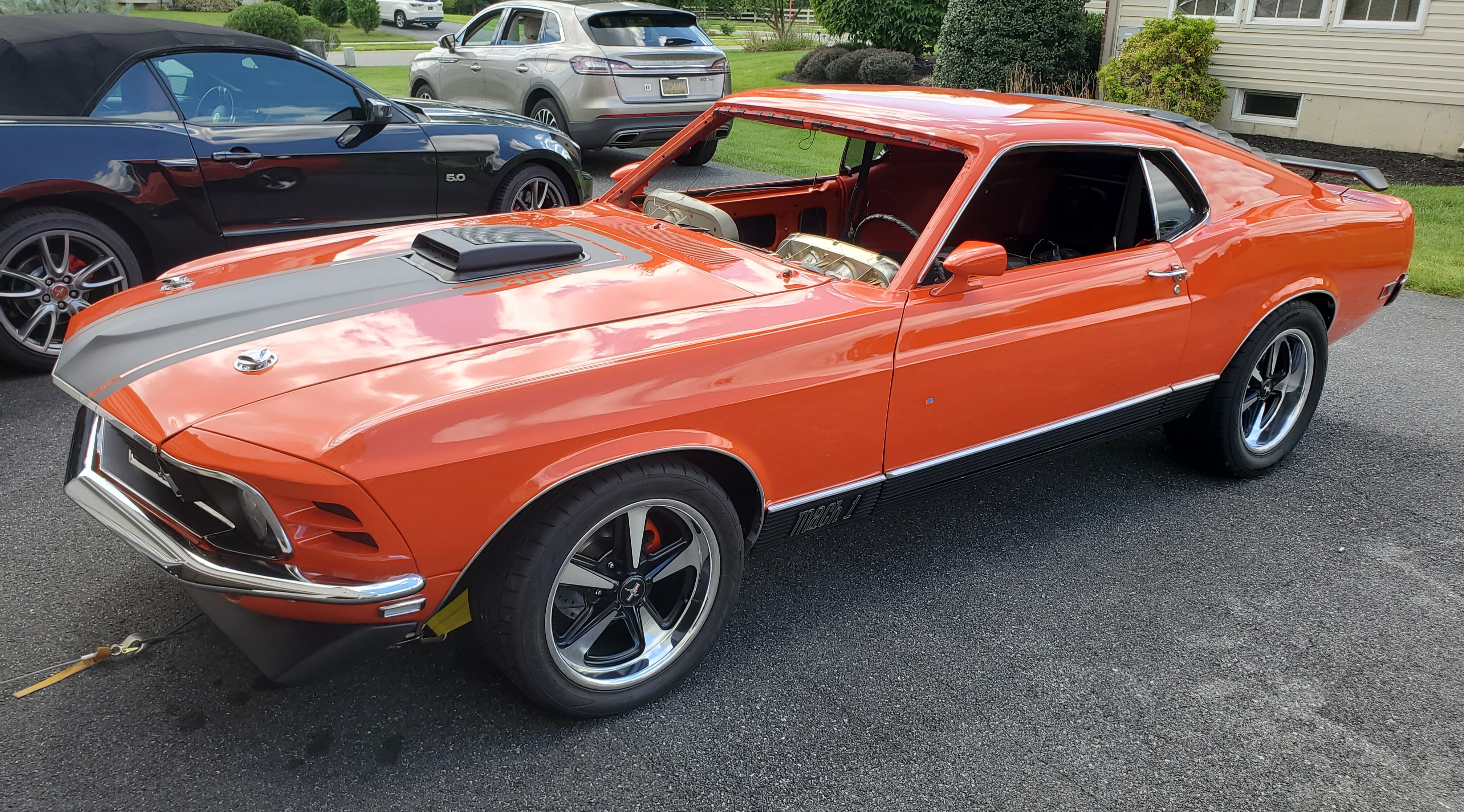
My new 1970 M-Code Mach 1 Project
Rich Ackermann replied to Rich Ackermann's topic in Project Progress Forum
Made a rookie mistake! I had a no start issue after wiring up my Sniper EFI with a Hyperspark Distributor, Ignition Box, and Coil on my 1970 Mustang with a 351 Cleveland, and I thought it I would post it hoping it might help others who experience a similar issue. I had my Cleveland rebuilt and my engine builder and he installed the EFI set up and ran the engine and then disassembled the EFI components and wiring before I received it. I installed it back in my car and wired the Sniper and Hyperspark components. I wanted to keep the wires neat, so I re-pinned some of the plugs and trim and lengthened some of the wires on everything but the Sniper itself. Before I go any further, let me describe the wire harness for the Hyperspark Distributor... The Distributor harness starts with a three-pin plug for the... 1) Red/Pink 12v ignition, 2) (center) Purple +, and 3) Green - crank wires. On the other end of the harness, the pink 12v is a single loose wire and the green and purple are pinned to the two-pin square plug to connect to the Holley Sniper. In the process of making the wire mods, I noticed that the two-pin square plug for the Positive Purple Crank and Negative Green Crank wires coming from the distributor were reversed (green to purple and purple to green) when plugged into the Sniper two-pin crank plug counterpart. I checked the Holley documentation that I received with all the components and nowhere did it mention that it is normal for the purple and green wires to be reversed when plugged in to the sniper EFI. The complete wiring diagram did not have the wire colors for these two wires. The Holley documentation did say to use the harness that comes with the distributor, but that was all it said. So I thought this must be a manufacturing mistake, and I re-pinned the wires to match purple to purple and green to green. WHAT A MISTAKE! For days I tried to diagnose my "STALLED" problem undoing all my wiring and tearing my hair out in the process. Even with Holley tech's help, we could not figure out why my Sniper was indicating the engine was stalled and was not getting a crank signal. Long story short... I was at a loss and ready to ship the Sniper to Holley for testing under the warranty, when I was going back thru some pictures I had saved and saw a sales picture for the Hyperspark Distributor, and in the picture I noticed that the wire harness shows the purple and green wires were also reversed in the plug. I went back and re-pinned those wires back to purple to green and green to purple and the dam engine started right up! So, DO NOT make the same mistake I made! Holley should provide a better explanation and tell the installer that these wires are intentionally reversed and do not change them. -
My new 1970 M-Code Mach 1 Project
Rich Ackermann replied to Rich Ackermann's topic in Project Progress Forum
Finally installed the rebuilt Cleveland. I had some clearance worries, but once I installed the Tremec TKO 600, which I had MDL machine the top covers on the TKO to provide more clearance on top to better match the stock alignment, my valve cover was no longer in contact with the brake booster....What a relief. Also my Sanderson Block Hugger shorty exhaust headers cleared everything, including the obnoxiously large GM style steering box I got from CPP. The next test was to install the shaker stack on top of my taller than stock Edelbrock Air Gap intake and hope it it fits under the hood. I used a (repro) 428 shaker base which is about 3/4" lower in height than a Cleveland base. First I had to re-clock the base to align the concaved area with the distributor. This turned the base from a 6:00 position on the 428 to about 7-8:00 o'clock on my Cleveland. With the Shaker stack in place, the height of the shaker scoop was perfect with the hood closed. Apparently the Cleveland sit farther back in the engine bay than the 428, so I needed to shift the plenum and scoop assembly forward on the base to fit thru the hood hole. Once I had it positioned and clocked correctly, I drilled new holes in the plenum for the mounting studs on the base. The most difficult part was fabricating two crescent shaped sheet metal filler pieces to close up the gaps between the base and plenum created as a result of shifting the base forward. these filler pieces were attached to the front and back between the base and the plenum. This created an offset ring on top of the base in a way like the factory Cleveland base has. Finally, I made a bracket to bolt to the back of the base to an existing mounting hole on the back of the Edelbrock intake to ensure the whole thing can not rotate on the carburetor since it is held only by the center stud thru the air cleaner lid. No clearance issues with my Holley Sniper EFI, or the Hyperspark Distributor. or with the throttle cable, which I had to add a small plate to the stock throttle bracket to extend it to align better with he Holley throttle linkage. I fabricated a mounting plate and mounted the Hyperspark Coil to the Edelbrock intake under the air cleaner base. Installed the front end components... Four row copper radiator, Aftermarket six blade fan, Alternator, Sanden Compressor, Saginaw P/S pump with a Ford factory A/C mounted cooler. I fabricated the top plate over the Sanden compressor to mimic the mounting locations used on the factory York Compressor and mount the P/S cooler and Idler pulley bracket to it, just as it was from the factory York. I had to fabricate the P/S pump bracket and spacers to properly mount the Saginaw pump. This took a lot of time tweaking it until it was aligned with the water pump and crank pulleys. Here are some pictures.... -
Thanks. Fortunately, once I installed the Trans my booster clearance issue went away.
-
Thanks
-
Well as some of you suspected, once I installed the Tremec TKO 600, which by the way I had MDL machine the top covers on the TKO to provide more clearance on top to better match the stock alignment, my valve cover was no longer in contact with the brake booster....What a relief. Also my Sanderson Block Hugger shorty exhaust headers clear everything, including the obnoxiously large GM style steering box I got from CPP. The next test was to install the shaker stack on top of my taller than stock Edelbrock Air Gap intake and hope it it fits under the hood. I used a (repro) 428 shaker base which is about 3/4" lower in height than a Cleveland base. First I had to re-clock the base to align the concaved area with the distributor. This turned the base from a 6:00 position on the 428 to about 7-8:00 o'clock on my Cleveland. With the Shaker stack in place, the height of the shaker scoop was perfect with the hood closed. Apparently the Cleveland sit farther back in the engine bay than the 428, so I needed to shift the plenum and scoop assembly forward on the base to fit thru the hood hole. Once I had it positioned and clocked correctly, I drilled new holes in the plenum for the mounting studs on the base. The most difficult part was fabricating two crescent shaped sheet metal filler pieces to close up the gaps between the base and plenum created as a result of shifting the base forward. these filler pieces were attached to the front and back between the base and the plenum. This created an offset ring on top of the base in a way like the factory Cleveland base has. Finally, I made a bracket to bolt to the back of the base to an existing mounting hole on the back of the Edelbrock intake to ensure the whole thing can not rotate on the carburetor since it is held only by the center stud thru the air cleaner lid. No clearance issues with my Holley Sniper EFI, or the Hyperspark Distributor. or with the throttle cable, which I had to add a small plate to the stock throttle bracket to extend it to align better with he Holley throttle linkage. I fabricated a mounting plate and mounted the Hyperspark Coil to the Edelbrock intake under the air cleaner base. Here are some pictures....
-
Bookem' Danno!
-
Are these holes needed for anything?
Rich Ackermann replied to lalojamesliz's topic in 1969-70 Technical Forum
The photo is of the LH frame shock tower area of my 1970 Mustang Mach M code. Metuchan Built Jan 1970. -
That also my understanding that Eaton was the OEM. OEM or not I have had no issues with the two sets of stock height Eaton leaf springs I bought for my 1970 and 1973 mustangs. Like all springs they look high initially especially if the car is not fully weighted down, so they take a while to settle down the normal ride height.
-
Are these holes needed for anything?
Rich Ackermann replied to lalojamesliz's topic in 1969-70 Technical Forum
Those look like the bolt holes use by the small block motor frame mounts, but I could be wrong. The photo is of the LH frame shock tower area of my 1970 Mustang Mach M code. Metuchan Built Jan 1970. -
Air Cleaner Vacuum Motor Question
Rich Ackermann replied to Past Time's topic in 1969-70 Technical Forum
I am late replying to this topic, but just in case it is helpful in the future. You can test the vacuum actuator using a brake bleeder pump. The vacuum actuator should hold at least 13lbs of vacuum without dropping (fast or slow). If it does not hold the vacuum then the rubber diaphragm inside is bad. I have disassemble them in the past and repaired originals by sacrificing a cheaper plastic version. I take the diaphragm from the donor and replace the old one in the original. The hardest part is separating the actuator cap from the base. Make sure you have no leaks with the new diaphragm as it is sealed to the base. Here are some brands of actuators that are very close to the originals in appearance and function that may still be available. Three things to look for when buy an aftermarket actuator the orientation of the tab with the mounting hole (should be at 11:00 with the vacuum hose port at 12:00) and the opposite tab (is at 5:00) to the vacuum hose port. The orientation and length of the hook that connects to the snorkel flapper. Finally the vacuum hose port size... some are larger in diameter. Some of the all metal Ford Air Cleaner Vacuum Motor correct type actuators are: Niehoff FE703 AC Vacuum Air Cleaner Motor Actuator Avatar VM 263 Vacuum Air Cleaner Motor Actuator Borg Warner EC518 D7TZ-9D612B Vacuum Air Cleaner Motor Actuator Borg Warner EC517 BWD Air Cleaner Vacuum Actuator Motor VA13 ---is incorrect because the mount tab is at 1 o'clock instead of 11 o'clock Some of the pictures are from when I restored a 1973 Mustang with Ram Air, but all actuators are basically all the same. A factory original 1973 date coded (D73) Ford Snorkel Actuator I repaired as I described above. 1971 - 1973 Mustang Ram Air plenum actuator example. Using a no longer available repro from NPD as a model, I took a snorkel actuator removed the tabs from the new actuator base and made a new base from sheet metal with the correct tabs needed for the ram air plenum. I then glued the new base to the new actuator with body glue. I then finished it in yellow chromate although the originals were mostly silver. -
My new 1970 M-Code Mach 1 Project
Rich Ackermann replied to Rich Ackermann's topic in Project Progress Forum
Hi, I think original flapper plates had two holes on each side as you describe. Mine a is Scott Drake repro and only came with hole on each side. Thanks -
My new 1970 M-Code Mach 1 Project
Rich Ackermann replied to Rich Ackermann's topic in Project Progress Forum
Hi Vicfreg, I bought the individual parts from Scott Drake. The parts are all steel. He offers kits base on engine type, but I with my Edelbrock Air Gap those kits would not work for me. I used a 2" x 14" air filter and a 14" spectra filter lid with a recessed center for the wing nut. I confirmed that the lid clears for flapper mechanism. On another note, did you finish your led lights in the headlight buckets? -
My new 1970 M-Code Mach 1 Project
Rich Ackermann replied to Rich Ackermann's topic in Project Progress Forum
Thank you. -
My new 1970 M-Code Mach 1 Project
Rich Ackermann replied to Rich Ackermann's topic in Project Progress Forum
Thanks. -
My new 1970 M-Code Mach 1 Project
Rich Ackermann replied to Rich Ackermann's topic in Project Progress Forum
It's been awhile since i updated all on my project. I spent a lot time on the electrical, the stereo, and the rear fold down seat, and dash components recently. Also, was waiting on my engine builder to get the engine done. Well the engine is back and I dropped it in. Was thinking I had an issue with the valve cover making contact with the brake booster and the Sanderson shorty headers hitting the CPP GM style steering box. Today I installed the tremec tko 600, billet steel fly wheel,, Quicktime bell housing,, Kevlar clutch with a hydraulic clutch that I bought from MDL. It went right in and all my clearance issues and concerns vanished now that the engine was level. What a relief! Furthermore, I had installed an Edelbrock Air Gap intake, which everyone told would not work with a shaker because the intake is too high. So, I decided to use a 428 air cleaner base which along with 351W has a lower profile, but also has a different offset. Well I can happily say I don't have a height issue and I just clocked the 428 base to align the distributor concave area and re-drilled the holes in the top to straighten out the scoop. I have to fabricate a offset plate to properly seal the base to the top (plenum), since the plenum is shifted forward about an inch forward over the base. The offset plate is an easy thing to do next up, wire up the Holley sniper and Hyperspark distributor and Ignition. Finish assembling the front end of the motor, and grill/bumper, exhaust, and interior. Finally the windshield and driveshaft. Then it should be road test ready. The last pic shows a good shot up from underneath the driver's side header, where you can see the clearance with the steering in and further up daylight between the valve cover and the booster. -
BTW: I am using an Edelbrock Air Gap intake with a Holley Sniper EFI on my Cleveland. I know everyone says it wont fit under a shaker (too high), but I think I have that solved. Once I get the trans mounted and the engine tilt set, we will see if I am right.
-
Yes. That's what I am worried about.
-
1969_Mach1, Yep, I noticed that the covers make it tougher to get to the plugs. Not to mention the Moroso rubber spark plug covers are obnoxiously large too. Does not look much better than it was in my old 1969 428CJ. Especially with the P/S lines running along the shock tower. I am spoiled by the space i have in the engine bay on my 1973 vert with a stock 351C H-code. I may need to find a OEM booster with a smaller diameter. Thanks
-
RPM Thanks. I think I can use the factory covers without an issue. I may end up going that way. I don't have the trany installed yet, so I noticed that the engine, which has the clutch and the heavy Quicktime Bell housing attached, is tilted backwards pivoting on the motor mounts. If I lift the bell housing up an inch or two, which by eye looks like thats where it will be when trans is mounted, I maybe okay (barely but okay). In the picture, the top shows the gap with the bell housing up 1 1/2 and the bottom with no bell housing support/lift.
-
Thanks. I am looking forward to it when I get the car on the road.
-
Yes its a aftermarket 8.0 inch diameter. If the factory diameter was 7.3 inches then that could explain it.
-
Its a replacement unit, I bought separately when I bought the brake kit. Its a 1967-1970 Mustang power brake booster kit for front disc brakes with MT.
-
Hi All, I could use some advice. I have a 1970 Mustang Mach 1 M-Code 351C 4v. The car originally had no Power brakes or P/S. I added after market four wheel discs brakes and a CPP GM style steering box. I have a set of Sanderson Block Hugger Shorty Headers and the valve coves are a pair of Ford Racing covers. That said, I dropped the engine in for the first time and everything looked real good. No header clearance issues, not even around the obnoxiously large steering box (See pictures below). What surprised me was brake booster is in contact with the back edge of LH (driver side) valve cover. Hard to say how much but I am guessing i will need to gain about 1/2 to 3/4 inch between the cover and the booster. A smaller booster may be the best solution, but is possible to dolly the rear edge/side of the valve cover inwards about a 1/2" without creating internal interference, and also can I do the same to the outer edge of the brake booster without creating an issue? I don't want to break the booster. I just don't know the booster internals. Anybody have a similar issue? Appreciate any insight and advice. Thanks, Rich
-
My new 1970 M-Code Mach 1 Project
Rich Ackermann replied to Rich Ackermann's topic in Project Progress Forum
Vic, The wood was only used with heat to mold the ABS plastic into the shape of the block-out plates and the tinted lens. I used heat to bend the ABS edges over the wood edges at a 90 degree angle. I cut the ABS at the corners to help create a "flap" that I could fold over. Making it easier to get the shape needed. Sorry I don't have more pics of the steps I took. Lost them a year ago when my phone memory became corrupt. Anyway, yes I used two screws thru the ABS plastic housing and thru the tinted plastic into the original block-out mounting holes in the Fender Cap. The spacers were there allow me to tighten the screws without crushing the ABS plastic housing. I drilled a small drain hole in the lowest point and also a hole for the LED wires to exit the assembly. I mounted with adhesive tape the LED strips in side the housing to the ABS plastic making sure there was a little bit of space inside the housing between the tinted lens and the LED strip. Once I was happy with how it all fit together and mounted to the fender cap, I used hot glue to seal and hold it all together. Below is a graphical drawing of the side view or profile of the housing with all the parts identified. I hope it helps make things clearer. If not, don't hesitate to ask .... -
My new 1970 M-Code Mach 1 Project
Rich Ackermann replied to Rich Ackermann's topic in Project Progress Forum
Hi Vic, I like what you did a lot! They look fantastic! But I agree they are very bright. I have some pictures of what did that I posted below, unfortunately its not much, so I will describe it as best I can... I made wood mold the same shape and size as the plastic block outs used on our 1970 Mustang. I then cut some thin ABS the same shape the plastic block outs but a 1/2 or 3/4 inch larger all around. I then heated and flexed the ABS around the wood mold. Nothing fancy as it would not be seen. Then using a flat piece of plastic tinted license plate cover (the kind you can buy at any auto parts store), I cut out the lens again the same shape as the plastic block outs, but a little oversize to ensure I had some overlap to marry the ABS enclosure together with the tinted lens. I then drilled the mounting holes thru both parts. This was a bit difficult to get the holes in the right spot and angled correctly the way they are on the original plastic block outs. I then temporarily stuck the LED Amber White switchback Turn Signal Indicator strips to the enclosure and drilled a hole for the three wires to come thru the bottom of the enclosure. With a little trial and error I was able to adjust them until they were position perfectly in each of the horizontal slots. My preference was to have the LEDs hidden when not on so the ports still looked blacked out as they originally did. Furthermore, I wanted to prevent the LEDs from glaring brightly, so I was prepared to add another layer of the tinted license plate plastic to darken the lens further if needed, but in the end I did not need to. Finally, the LED strips are weather/waterproof, but I felt the enclosure sealed properly with a small drain hole in the lower bottom end would help keep them clean and dry. I originally used a heavy duty LED two prong Flasher relay in the factory plug and it worked just fine, but later I decide to try a three prong Adjustable flasher relay to help keep all the incandescent bulbs I still had along with the turn signal arrows in my side vie mirrors and these LED switchback strips all in better harmony. The three prong still fit in the two prong factory socket with the third wire being ground, so I just wired it to the dash. I made mine about two years ago now. The LED Amber White switchback Turn Signal Indicator strips I used were 12v compatible without a transformer which made it easier to thread the wires. Today, I see that there are improved 12v LED switchback strips that are one continuous rope light and cat be cut to length as needed. I may have to try these next go-round. Here is what I used... The last picture is one of the new rope like LED switchback turn signal indicators I found on ebay. I think these would work even better than the ones I used. BTW: I bought the LEDS on eBay and the two prong heavy duty flasher relay from NAPA, and the three prong adjustable on Amazon.