
Rich Ackermann
-
Content Count
362 -
Joined
-
Last visited
-
Days Won
30
Everything posted by Rich Ackermann
-
 I am hoping someone can provide me with the measurements for the Parking Brake Bracket location. See the diagram below. I am looking for the distance in inches from the Transmission Cross-member (A) and from the floor support (B) to the two rear points on the bracket. Thanks in advance for your help, Rich
 -
Need help identifying a part
Rich Ackermann replied to Rich Ackermann's topic in 1969-70 Technical Forum
Thanks all. They look different than the factory ones on my fastback. Fortunately, I will not need them as I still have my orginals installed. If anybody wants these let me know and I can mail them to you. -
I have replaced cowl, floors, seat pans, torque boxes, firewall, doors, rear dropdowns, and quarters on my 70 Mach. I have no idea what these parts came from and where they go. Any ideas? Thanks!
-
That number is for a Torino or Mercury Montego. I think the housing is the same but the pedestal is different from a Mustang. Are you still looking to buy a 2100 carb. I have one. Maybe we can work a trade.
-
John, I just PM'ed you. Thanks
-
Quarter Panel Replacement Question
Rich Ackermann replied to Rich Ackermann's topic in 1969-70 Technical Forum
Thanks all for taking a moment to share your experience and expertise. You have all given me lots to think about as I prepare to take on this new challenge... quarter panel replacement. I will let you know how it goes. -
Looking for good 69 to 73 sport mirror housings and/or pedestals. Don't care about the rest of the assembly... Broken or missing glass and cables are ok.
-
Still looking for Cleveland 2v heads? I have a set.
-
Quarter Panel Replacement Question
Rich Ackermann replied to Rich Ackermann's topic in 1969-70 Technical Forum
Got it. I am planning on TIG welding it and moving around the seam to keep the heat down. Do you recommend flanging it with an overlap instead of overlaying the new panel on the old and cutting thru both the new and old and then butt welding the seam? Thank so much! -
To anyone who has replaced their Fastback quarter panels. I am getting ready to replace my 70 fastback original quarters with Dynacorn Skins. The skins replace the old panel from the front door jamb lip to the rear quarter extension lip, and from the rocker, wheel well lip, and drop down on the bottom of the quarter to about two inches over the top of the quarter shoulder. See the picture attached. My quarters are mostly good and only need to be replaced from about halfway down the quarter, this would include the section at the door jamb/rocker in front of the wheel well, the wheel well lip and the lower quarter behind the wheel well where it meets the dropdown and the tail panel and valence. So my question, is it best to use the entire replacement skin, which means cutting the old quarter panel over the shoulder (just below the quarter window and thru the top of the trunk deck area), or is it better to cut the old panel a few inches down the side of the panel below the top of the quarter, and trim the new skin down to meet it? Seem to me, that it would be easier to patch them together on the side of the panel where you have a more "wide-open" surface area to work it. I would appreciate feedback, from anyone who has done this before. Thanks
-
There are kits like this which require more radical mods: https://www.heidts.com/part/ifs-for-64-70-mustang-and-67-70-cougar-and-60-65-falcon-and-64-65-comet/ or Coilover upgrade kits that basically bolt in where your old suspension did: http://www.totalcontrolproducts.com/fcoc-fd.html
-
I really like your choice of motors. The SN95 Mustang motor is the same as the T-bird motor for the same years (1989-97) I tried using a while back, but I chose not to use it because the vertical diameter of the mounting disc was a very tight fit and I did not think it would not clear the housing. Looks like you trimmed the bottom and top of the mount (circle with the mounting clips on the back of the plastic mirror base) and removed the clips off the mirror base. Question: Even without those clips on the top and bottom the base will stay clipped firmly on to the motor (disc)? I may have to give it another try.
-
Yes I used the two wire with the built-in sequencer. Yes I hooked it up to an electronic flasher module when I first got them and it still worked. I will video it. Another option is to add a small capacitor in line with the mirror sequential lights, but I have not experienced a need for it. Here is the video. The flasher helps to keep the sequential arrows in sync with the other flashing bulbs. 20190803_015147.mp4
-
Center console is an option. 69 have the cigarette lighter hole in the front of the compartment. On a 70 console you drill a hole thru the woodgrain top. Under the woodgrain in that spot is a space where 69 years had the seatbelt buckle holder. Just a few ideas.
-
Well I still am working on refining the mod before I shared it all. I have not completed the drivers' side yet and I am looking at using different motors. Here are pictures of what I have done so far....
-
The glass is a "standard" reproduction you can get from CJ or any other distributor. They are semi transparent and dont have the mounting back plate so the LEDs will show thru the glass from the back.
-
A relay is the way to go. The headlight switches are prone to overload issues, especially as they age. Another possibility is to get a 70 headlight switch (A 70 switch looks the same and has exactly the same plug configuration but must be internally different based on part #) and connect the P wire to R.
-
I always wanted to add motorized side view mirrors to our cars. Well in my case my 1970 Mach 1 project car. I have seen posts where folks have adapted 2015 Mustang side view mirrors to a 1969 Mustang, but I wanted to have a more original look. Well with some research, a few parts from a (non-Ford) donor car and some fabrication and experimentation, I made it work. As an added bonus, I incorporated sequential LED directional lights to the package. I made very little mods to the original mirror. Obviously a hole thru the inside of the pedestal and the housing where the two meet for the wires. Also needed to fashion a custom mount bracket inside to mount the motor and mirror. Check out the video attachment file at the bottom of the passenger side it in operation..... Motorized Side View Mirrrors.mp4
-
The map light and glovebox door plunger ground (black wire #57 in the electrical diagram) flows back thru the clock harness and then back to the printed circuit board and then eventually to the chassis. The 57 black ground wire connects to the two end terminals on the map light switch with the positive wire on the middle terminal.
-
I really like the looks of the shaved rear bumper. Like to do the same to my 70 Mach 1 project. Love to see more pics of the bumper mods. Did you fabricate your own bumper mounts to pull it in? My original plan was to keep a very original appearance, but I am slowly moving further and further away from that. I plan on stroking the Cleveland to either a 383 or 408 with an Edelbrock AirGap, Holley EFI and dual sync, and adding upgrades such as Borgesson P/S, Classic Air A/C, Power Windows, Power Disc brakes, a Tremec TKO-600 5 spd with Hydraulic Clutch, upgraded suspension (possibly a Global West kit), TinMan Subframes, and Eaton TrueTrac anti-slip Diff. Also going with TMI interior.
-
First, there are two switches involved here... one on the light fixture and the glovebox door plunger switch. I assume you are referring to the button plunger at the glovebox door. The Glovebox door switch is normally a ground connection and will complete the circuit (light will come on) when the switch plunger is extended (glovebox door open). This operation overrides the ground at the light fixture switch. Press the plunger (close glovebox door) and the light will go out. With that said, there is the switch on the light fixture itself that will also make a ground connection when in the "on" position even with the glovebox door closed. The ground (negative) connection is thru the black wire and the positive is thru the green wire in my picture. Does the light turn on and off with the light fixture switch without the glovebox switch connected, it should work? If not then you may have a ground issue with the source ground wire. Maybe you have a faulty Glovebox switch where it is still grounding even with the glovebox door closed, or the negative ground and the positive wires are crossed at your power source, but I would think this would cause a short?
-
1969 M code Autolite 4300 stock jet size?
Rich Ackermann replied to Yrdnal's topic in 1969-70 Technical Forum
The 4300-A Square bore. This may help identify what you have.... 4300A, 441 CFM (1967-1969) The first version of this carburetor was released in 1967, replacing the 4100 on all Fords excluding the police package 428 CID and 289 CID high-output engines. 4300A 441 CFM specs: · 1" primary venturi · Primary throttle bore: 1-7/16" · Secondary throttle bore: 1-9/16" The 441 CFM carburetor was found to run too lean for the 390 CID engines; hence, the 600 CFM 4300A was developed the following year for these larger applications.[3] The 441 CFM 4300A was discontinued after the 1969 model year in favor of the two-barrel Autolite 2100 carburetor. 4300A, 600 CFM (1968-1974) Due to the limited flow of the 441 CFM version of the 4300A, a 600 CFM version of the same was released in 1968.[1] By 1970, it was factory supplied on most Fords equipped with the 429 and 460, in addition to vehicles with the 351 Cleveland. The 1973 and 74 versions were labeled Motorcraft. 4300A 600 CFM specs: · 1.25" primary venturi · Primary throttle bore: 1-9/16" · Secondary throttle bore: 1-11/16" -
This may help... Here is the wiring on my 70 mach. I have a repro map light, but the rest is factory. The repro map light male/female plug did not match up with the male/male plug on the original wire harness. So I made a pigtale adapter to connect them.
-
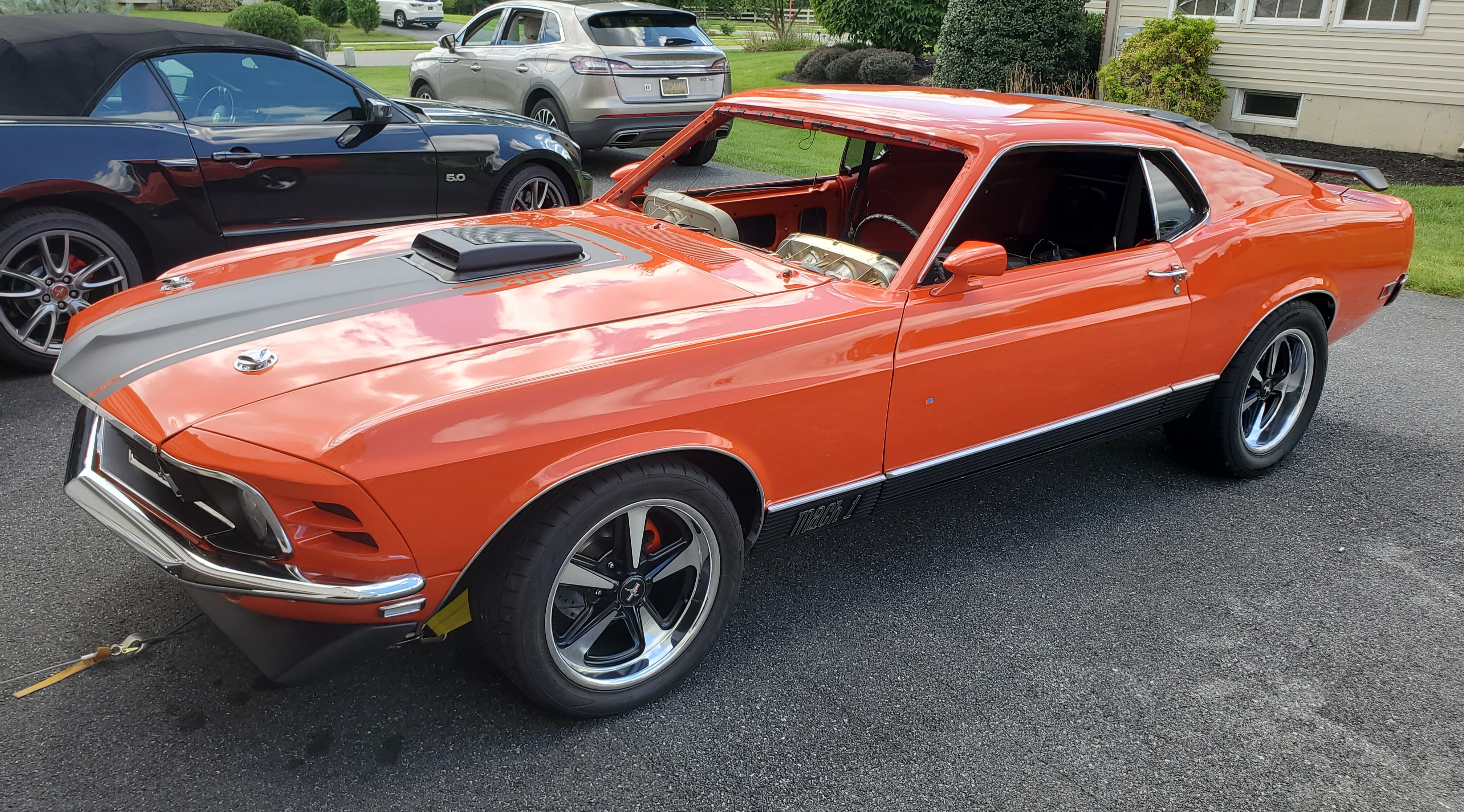
My new 1970 M-Code Mach 1 Project
Rich Ackermann replied to Rich Ackermann's topic in Project Progress Forum
Thanks! I have a long way to go. Needs rear quarters and trunk drop downs and maybe a tail panel. Then I start panel fitting, primer, block and sanding. -
My new 1970 M-Code Mach 1 Project
Rich Ackermann replied to Rich Ackermann's topic in Project Progress Forum
Moving on with replacing the footboard or lower part of the firewall, top of the driver side torque box, and floor pan. I am relieved that the rockers are great shape. Decided not to replace the floors under the rear seat as they are also in great shape, so I just cut the full floor off at the top of the riser. Also using a one-piece seat support and Tinman sub- frame connectors to add some rigidity.

