

stangme428
-
Content Count
1,881 -
Joined
-
Last visited
-
Days Won
5
Posts posted by stangme428
-
-
nice! should be awesome!
-
It's awesome, only change I'd make are the bumpers and front window trim. Need to match the color of the rest of the car. But, a very minor detail.yep they have a carbon fiber bumper option.... not sure about the window trim tho...
-
thanks EL70gato ... funds sent on 8/23/14parts received 9/3//14 item as described and packaged great! thanks!:clap::punk:
-
-
I ordered a set of Tommyzees subframe connectors - should arrive by September 15th, 2014.
These look well built and allow for additional mounting points - also plan on welding flat plate and gussets for the roll bar to replace the plates currently provided with the roll bar kit.
update *** received on 9/10/2014 -- great quality!
-
great pics and im sure that ride was awesome! great work!:punk:
-
I know! but hey.. great minds think alike! i dented the lower valance the second time i drove it up on the trailer to head to the exhaust shop ... my first thought was ... glad i didn't have a chin spoiler... lol .. dent popped out with a little help.
--- update --- its freakin on back order!!! argh!
--- update --- shipped on 9/4/14
hahah copy cat!!! lol, jk.
glad u did it! I know for sure my CF Anvil Chin Spoiler wouldn't last long its thin and flimsy it would have definitely cracked if something hit it.
I love the the new chin spoiler it even comes with all the hardware and instruction sheet.
-
Thinking of the Maier racing fiberglass hood and the anvil fiberglass cowl panel
has anyone used the maier racing hood? or the anvil fiberglass cowl panel? i know a few have used the anvil carbon fiber cowl panel ... but wasnt sure of the fiberglass parts...
thanks!:thumbup1:
-
Ordered! Thanks rwcstang for the motivation! i was trying to decide on the anvil spoiler or the ABS ... ABS seems more practical.. im sure ill hit stuff!:thumbup1:
while my massive boss 429 racing scoop is okay ... im thinking of going with a CF or fiberglass stock hood with the anvil cowl panel piece... while i like some aspects of the anvil extractor hood ... i like the stock "ironing board look" :tongue_smilie:
edit -- that was quick... i like the Maier racing fiberglass hood
and the anvil fiberglass cowl panel posted a question in the garage of any
fiberglass users...
thanks!:thumbup1:
Quote:
Originally Posted by stangme428 View Post
rwcstang - every time i see your car it reminds me to order a chin spoiler!
DO IT! I bought mine from CJponyparts http://www.cjponyparts.com/front-spo...ck-1969/p/FS3/
decided to put aside my Anvil CF chin spoiler for an OEM looking one.
-
rwcstang - every time i see your car it reminds me to order a chin spoiler!
-
18x9's all 4 corners.... 275x35's all 4 corners. vintage venom front brakes with spacer that comes with the kit. no spacers on rear.. but i need a wider wheel to match the width of the front..:thumbup1:
-
thanks EL70gato ... funds sent on 8/23/14
-
awesome friends and forums like these make it work... ask me how i know! good times.. congrats!:thumbup1:
-
yep yep ... one of the mods to the cleveland heads is to raise the floor on the exhaust port... some use port plates that place a "tongue" on the bottom of the port to.... raise it.. :thumbup1: most of the aftermarket aluminum cleveland heads already have the exhaust port floor raised..:thumbup1:
-
nice build... every TCP product they have... almost :-)
looking good!
-
great stuff guys!!:punk:
-
ok -- so Andy replaced the cam in the ORIGINAL switch, soldered and heat shrink on all the connections, removed two bulbs per tail light housing. Andy HATES anything electrical or wiring... but i talked him into it... plus its keeping me from going insane after being at the hospital all day with my dad.
brakes now work, turn signals now work ... no hot wires.. more testing to follow.
but... progress! when i get back home ill check the current draw and go over all the wiring to the rear of the car again, and install the sequential LED tail light kit once i know we wont blow them up...
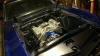
also installed the new scott drake aluminium/billet recovery tank... its for 65-68 but i think it looks good in the 69 engine bay.
-
tease pics! more more!
-
Just my two cents but there has to be something else going on here. That design was in service a decade or more. Some unseen issue, overload, or short/semi short seems to be taking it's toll?Brake switch maybe somehow?
No clue how to help though. I haven't looked at the wiring schematic / runs for this in a long, long time.
Good luck and update us when you get it... and you'll get it. :-)
Stephen
yep .. we will find it.. what is funny is this circuit is so simple .... the switch makes it difficult.. lol..
we are replacing the cam on the ORIGINAL turn signal switch... removing two bulbs a side and testing a few things.. :thumbup1::tongue_smilie:
-
More Parts . Call Mark 248-904-7134im interested in the passenger side insert with clock.... PM me with a price when you have time.:thumbup1:
-
well i had it in mind when i was building my 69 coupe... but i went with a 408 clevor instad of a 428 and i couldnt afford the IRS setup:thumbup1: after i found all the rust under my original vinyl roof and had the roof replaced with another coupe roof... i will never have a covering on my roof again :tongue_smilie:
-
ok - so while im at the hospital with my Dad, Andy troubleshot the turn signal / brake light problem and fed me the info last night. skype works great when you need it
so, looks like the new... 2nd turn signal switch plastic deformed due to heat... melted? really.. no fuses blown, 10A fuse.
so, lets do the math... according to what i have found online:
1157 filament in circuit is 6 ohms
using ohms law to calculate current across each drop:
12v/6ohms=2a
so using kirchoff's law basically the sum of the currents are equal to total current.
It = I1+I2+I3
6a=2a+2a+2a
so, really... the plastic deformed when the brake is applied? hmmm so when both brake lights are on with 6 bulbs thats a 12a load through the turn signal switch ... no blown 10a fuse.?
thinking back to when this first happened with the 1st new turn signal switch, it was when they placed a brake lock device on the brake pedal while setting front alignment... brake was on for an hour i think... brake lights worked on the way in... not on the way out...
but that turn signal switch had a bad rivet on a wire... very small head on the rivet holding the wire eyelet on. at least thats what i found... maybe the plastic deformed...
so i guess i can go one of three routes....
replace with the LED tail light kit i have from mustangproject.com ..
go with 1157 led replacement bulbs..
or if im staying with the 1157 bulbs, insert a relay for the turn signal circuit and brake light circuit and switch the relay with the turn signal switch, reducing the load on the turn signal switch.
never a dull moment...
-
OMG:tongue_smilie: that is one of the most elegant and sexy designs ever! beautiful car!
yeah i would be smiling too! :thumbup1: congrats man! has to be fulfilling to have the skills to work on cars at this level and to see your work in the end on something that special and historic! great stuff!
:punk:
-
Protowrxs -- Arduino stuff me too... have it all planned out and tested out of the car with proper voltages etc. but not in the car as of yet...
as for the 3D need it seems we could use a better design for the turn signal mechanism than what was original and is currently being reproduced.. im not sure if its a materials problem of the reproduction, too flexible or too stiff... or if the original design was limited. I do know i am on my 2nd aftermarket unit and its been mechanical problems so far that have caused electrical problems. i.e intermittent contact due to flex of plastic or design limitation. bad rivet holding eyelet.. mechanical connection. etc.
i have not researched the different materials from makerbot to understand if i spend time scanning in a broken down version of the turn signal switch... if the material stiffness or flexibility will be any better than what is currently being used... im a electronics/computer geek.. not a mechanical engineer.. :tongue_smilie: so necessity is the mother of invention... maybe we need to all start a thread to jump in and design a better turn signal switch...:thumbup1: lord knows it would take all of us.. none of us have a lot of spare time....
Looking forward to your Arduino stuff, although I'm gong back old school for the overall, my robotics hobby and Arduino past keep popping in my mind for some little things.What is the 3D printed need? I hoping to design and print some basic gauge adapters for the side gauges instead of the cut up setup I did before. I'm not much of a designer though. :-/
Stephen
69 coupe build
in Project Progress Forum
Posted · Report reply
no scoop time! -- okay so we removed the Boss 429 racing scoop last night... so im liking the Maier Racing eliminator style hood in fiberglass... so we shall see.. dreaming of the Agent 47 with the ducts but... dont think that is likely... more to follow as .... already have a painter to match the color and layout on the new hood... :tongue_smilie::clap:
excuse the dirt... other projects behind the 69.. no time to give her a bath of late...