


foothilltom
-
Content Count
771 -
Joined
-
Last visited
-
Days Won
2
Posts posted by foothilltom
-
-
Hey guys, just for "closure" (as often there is none in these threads), I chose to sell the 2nd gen C4 I had bought as a stop-gap (per my original description). Son limped the car up from LA and I set about re-building his original C4 first gen tranny over a 3 week period. Never had done that before, so I was quite uneasy. Took my time, took a zillion photos, and found at least 3 significant issues that would have explained the bad behavior.
Anyway, C4 is back in, new servo, o-rings, bands, clutches, steel, thrust washers, bushings, seals, etc. and the Stang is back on the road. Only set us back the price of the master rebuild kit so I'm going to call it good for now. I'm sort of trivializing a rebuild that my hair standing on end at times, but it all worke dout.
Thanks again for all your input.
Tom
Mach1 Driver and lalojamesliz reacted to this -
Hey guys, thanks for the responses. Like anything, you learn as you go and I just learned that buying what I thought would be a "straight up, bolt-up, replacement" to buy some time was probably not well thought out on my part. This C4 came with a torque converter, so at least I'm covered in terms of the spline difference in this generation C4.
I was concerned about going with a C5 for fear of needing to do a lot of modifications, but it sounds like (from dcm0123's memory) I'll need to be doing some ahem, modifications to the tunnel to make the larger bell-housing fit. Maybe that'll go easy, but anytime the sledge is coming out, it's probably a sign of some bad planning.
I understood the C5's have the lock-up converter, but I've also read that the early C5's had issues with the lock-up? Anyway, I got tunnel vision trying to get a straight swap to buy time for me to do a careful rebuild of the original tranny, but should have stopped long enough to think about all the improvements that have come
Maybe I'll just unload this 1971 vintage C4 and start poking around for a C5 or open up the whole spectrum of AOD, etc.
Thanks again.
-
Hello my brethren. Damn, it's been a long time since I posted here. I hope you're all alive and happy.
My question is regarding "fitment" and compatibility of a 2nd generation C4 (1972 to be precise) with a 1969 coupe. Filling in some details...
- original 302 swapped out for a 351W, shorty headers some years ago
- original 1969 C4 stayed in car, was never super awesome, recently slipping bad, fluid smells burnt, etc.
- original C4 absolutely needs a rebuild
For logistical reasons (son uses this as his daily), I decided to buy a tranny that aledgedly runs good with the plan to quickly swap out the ailing original C4, put this one in, and then buy some breathing room for me to rebuild the original C4. Hence my question about compatibility and fitment.
Ideally, it won't require drive shaft alterations, but I do wonder if the different bell-housing, dipstick into pan type tranny may pose fit issues with shorty headers, for example.
In summary, does anybody have any direct experience with this, knowledge of physical dimensions being mostly the same (or not) between the 1st and 2nd generation C4?
Thanks very much in advance. My son and I restored this coupe when he was 14. He's 29 now and it's his daily driver. I'm 59 now and still learning.
Tommy D
-
Hello all,
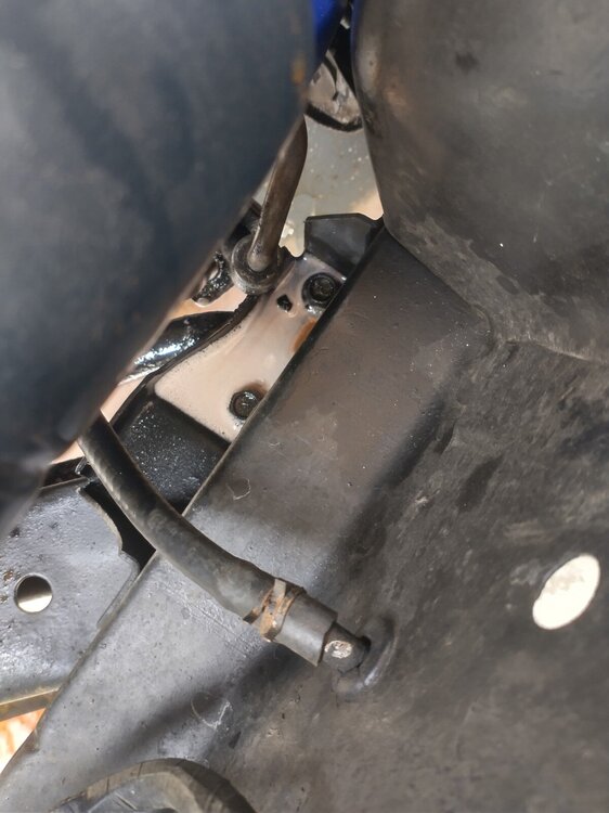
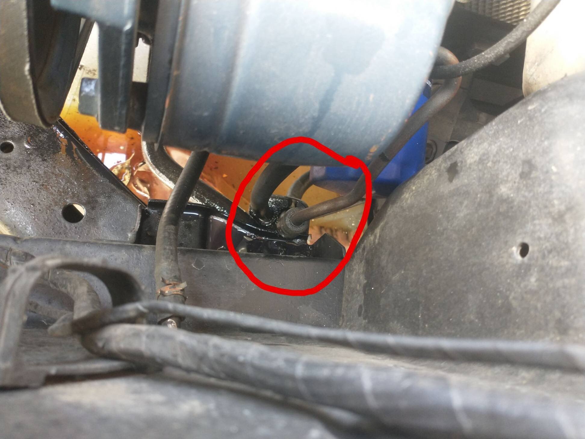
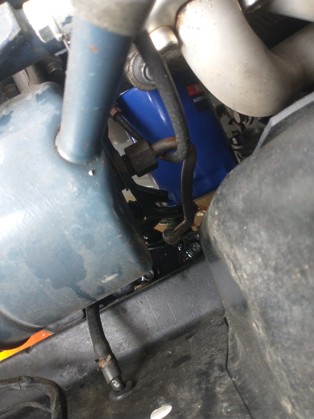
While parking my car I was met with wafting smoke from the engine compartment. I popped the hood to discover a significant amount of fluid coming from what I believe is the high pressure hose of the power steering pump - specifically the flared coupling that connects the metal tubing to the rubber. It squirts out quite a bit of fluid as I turn the wheel (engine on). The leak appears to be from the rubber side of the connection.
I am hoping to get some help identifying exactly which part I will need to replace. There seems to be some variety in these hoses for each model year. I think the part begins with 3A719, however, there seems to be several subtypes indicated by a letter. One forum suggested the VIN would tell me, which might make my car the "F" subtype? For context, the pump is original and was attached to a 5L 302 with a 4 barrel, however, I rebuilt a 5.8L 351W, which I have been driving everyday, without incident, for the past 8 months or so.
At this point, I know nothing of why this happened, and I understand it can be a variety of things ranging from a bad hose or clog or bad everything. For now, my main goal is to track down some kind of part number I can use to order a replacement for this section of the hose assembly.
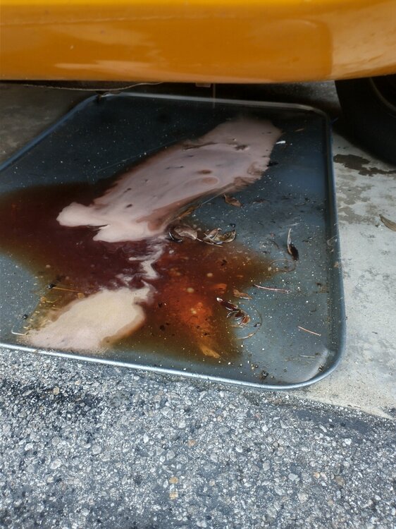
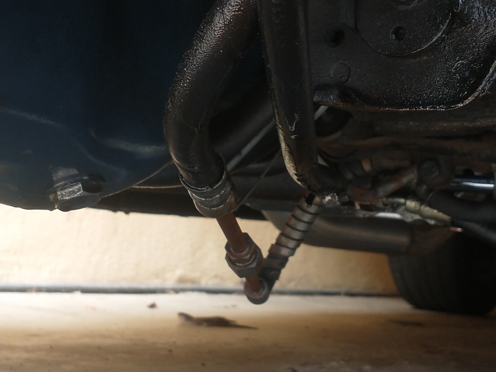
Appreciate any help in advance. The photos below show a driver side/top side view of the PS pump and the hose. After running the car a second time to confirm the location of the leak, the leaking fluid came out much more frothy and pink. Some of the other fluid in the picture is transmission fluid, which is from an old leak I am already aware of. I also included a picture of the underside to help identify the general shape of the tubing. Hope it helps.
Thanks.


-
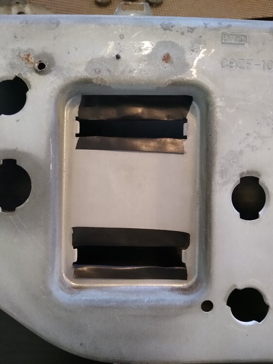
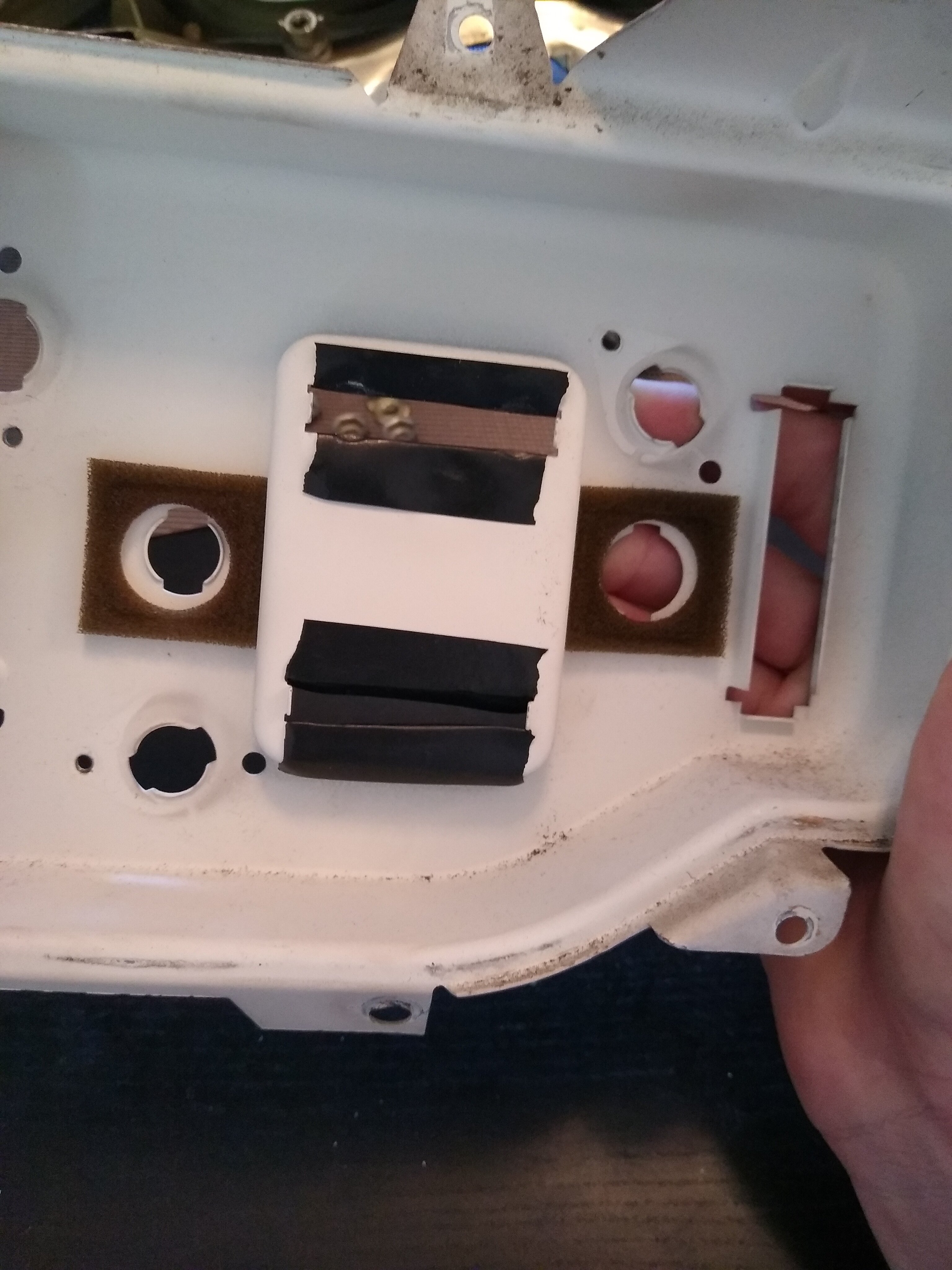
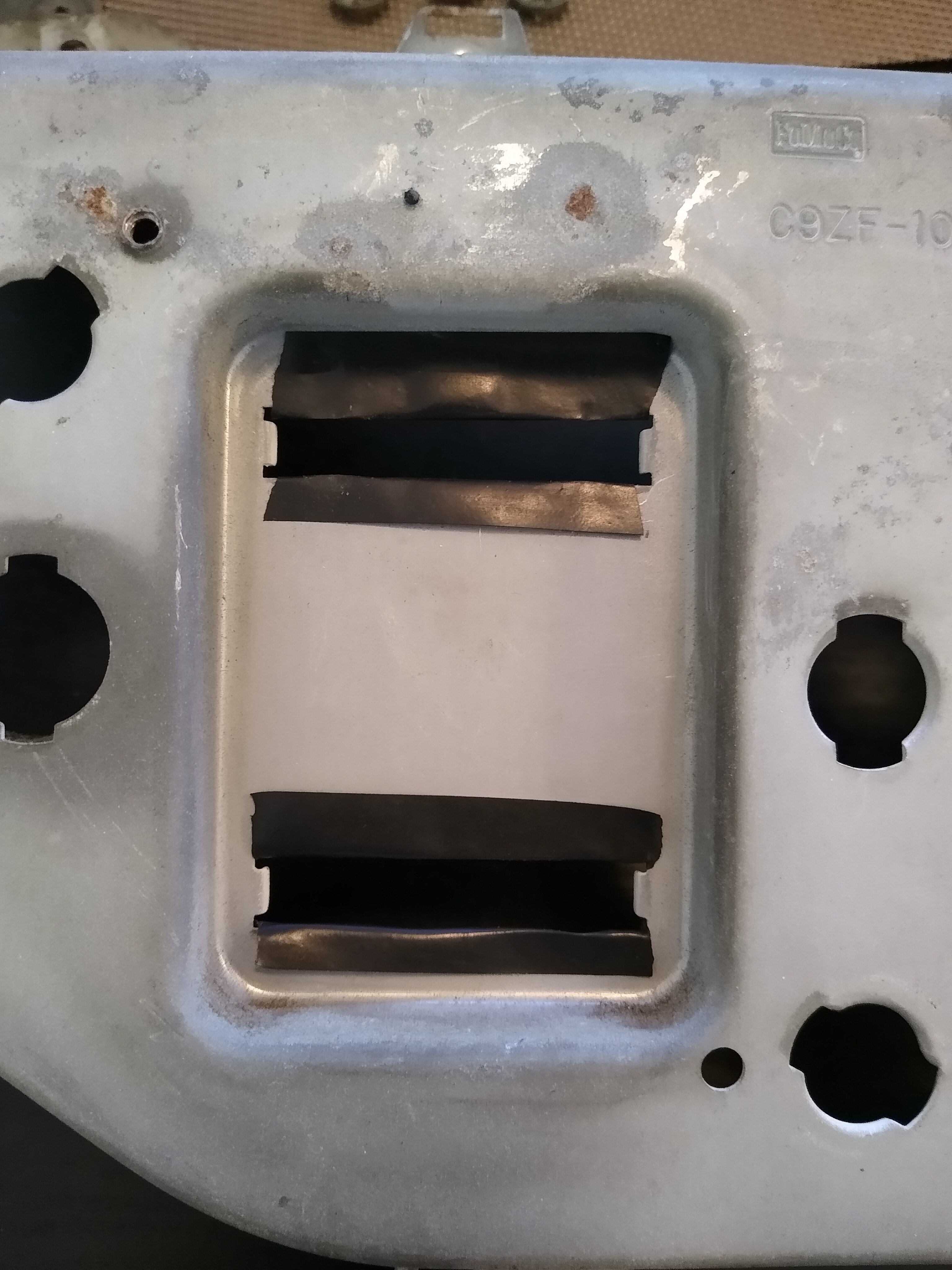
Last update for this post. After much troubleshooting, the fuel gauge problem was a re-assembly issue with the cluster. Even though the insulation brackets were in the right spot, the posts on the back of the gauge were contacting the cluster housing, grounding them out. I put some electrical tape around the inside of the housing where the posts slide through and it worked. Seems like a bad design, in my opinion, but it worked for 15 years before I messed with it so what are you going to do?
Got the idea from this video I found in an old forum. Hope it helps somebody else.

 69RavenConv and Mach1 Driver reacted to this
 -
They do. Also, dome light, heater light, courtesy light in the ignition, high beam switch, gear shift light - all working properly.
-
***SOLVED***
First off, I would like to thank you all for your help. Between all of your insights I was able to figure out the problem.
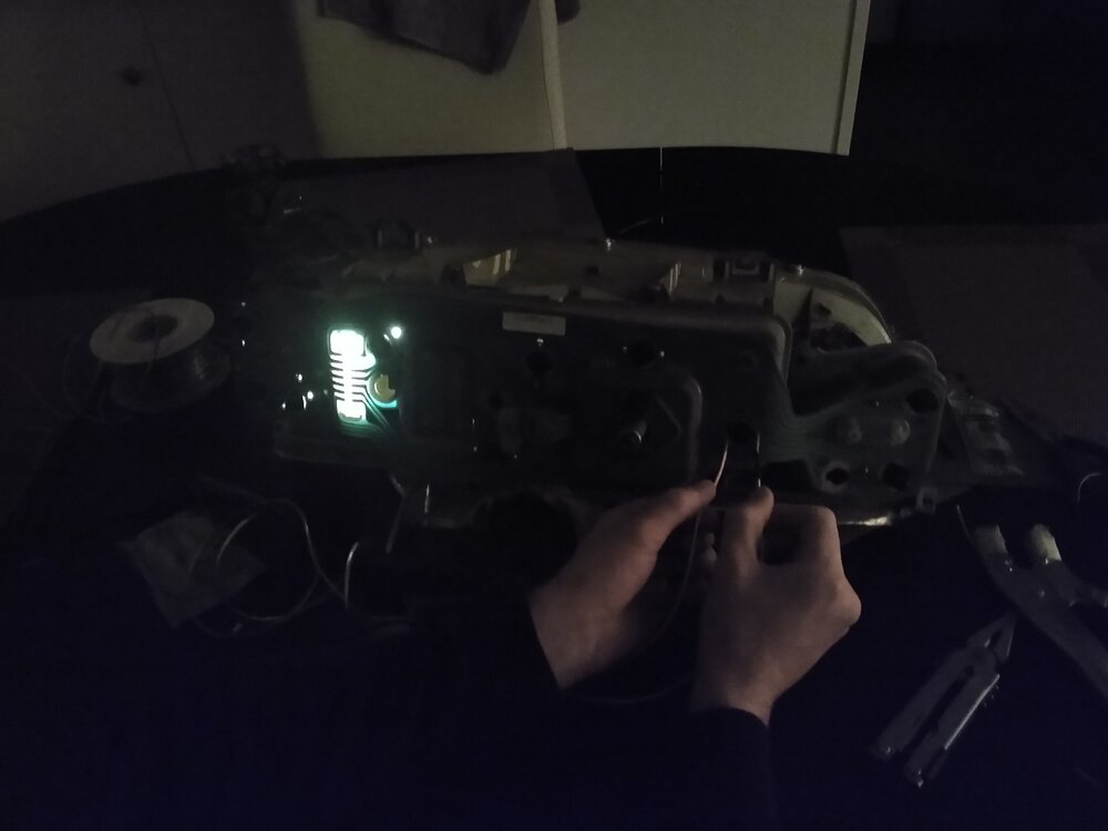
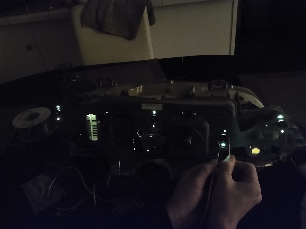
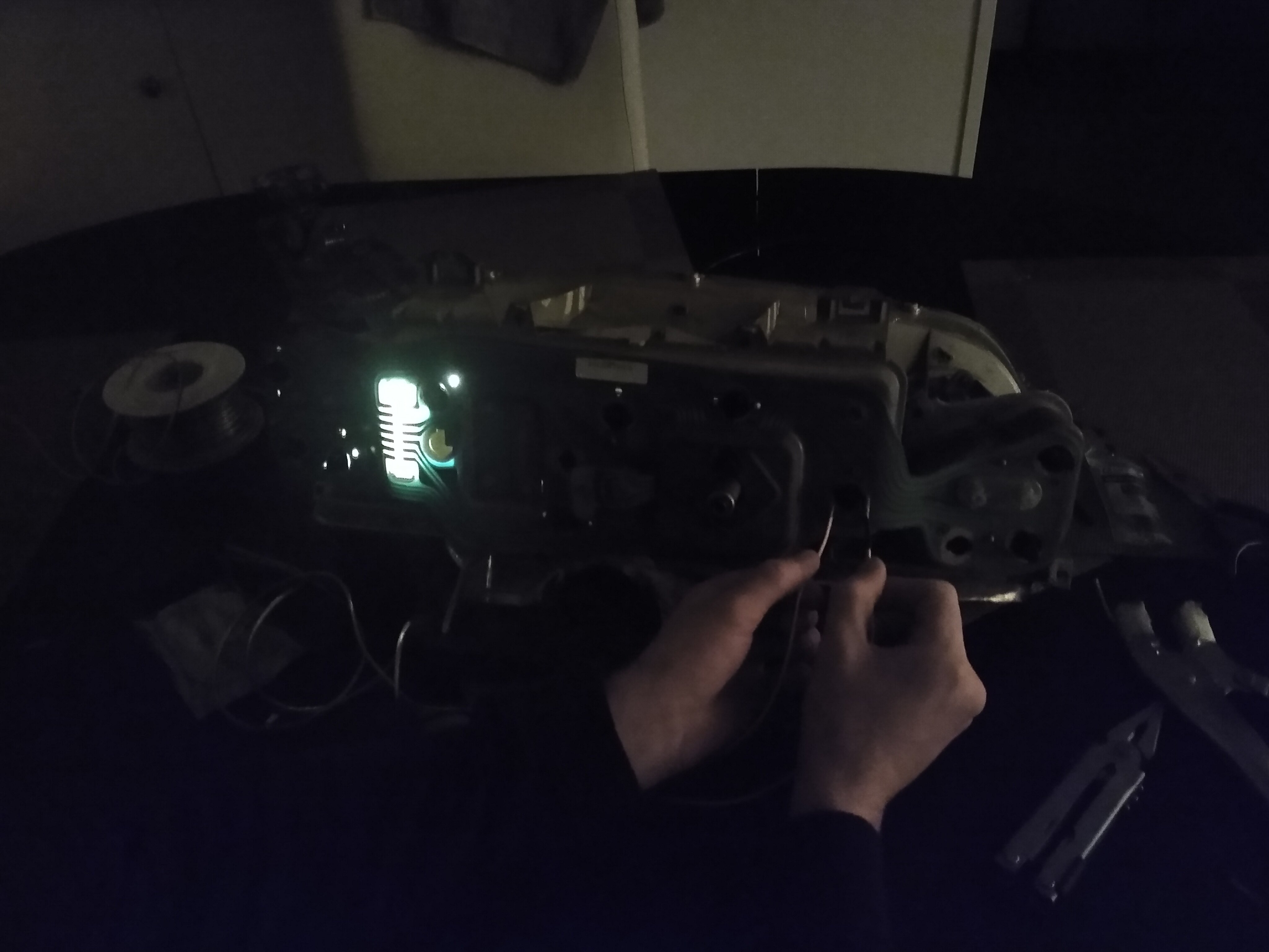
LONG story short, I hooked a 9V battery to some speaker wire and started poking my fully assembled cluster (now on my kitchen counter) until lights started turning on. To my surprise, sometimes almost all of the lights turned on! WEIRD! After a while I noticed a pattern that when I put voltage across each light socket, one of two things would happen: 1) Only two lights would light up OR 2) All of the other lights besides two would light up. This would happen after changing the polarity of my test by reversing which side on each socket I had the "positive" and "negative" cables from the 9V battery.
I then checked the forum to post my findings and saw what @danno had said about the insulating brackets so I took apart the cluster again and made sure they were in the correct position. Once I re-assembled the cluster and repeated my earlier test, I got the same results EXCEPT now two different bulbs were lit up (or not lit up depending on the cable polarity).
Once I bashed my head against a wall a few more times, I thought back to what @Midlife said about polarity, and even though the bulbs I purchased have reversible polarity, and, therefore, should not care how they are installed, I thought maybe, just maybe, technology back in 1969 wasn't set up to handle reversible polarity.
I then, in the proper "positive/negative voltage flow" scenario, removed and rotated each bulb, that wasn't lighting up, 180 degrees and BOOM. All bulbs work as intended. What a relief.
TLDR: Even reversible polarity LED bulbs bought from modern manufactures are not reversible in this context. I have no idea why and random chance of how I chose to install each bulb has been my downfall all along. I will definitely be marking my lights and light sockets with a pen from here on out.
Anyways, a test drive to make sure my gauges were working revealed that the only casualty is my fuel gauge, which does not work anymore. @danno this gauge had the insulating brackets in the correct place all along so i'm not too sure why it's suddenly not working, but I am taking the win for tonight.
Pictures attached of my 9V test for those who are curious. I hope this thread helps others who have issues with after market LED's.
 Mach1 Driver and RPM reacted to this
 -
@danno What is this flextape that you speak of? Is that another name for the circuit board? As far as I know there was not any insulating material on the gauges - unless you count some rectangular plastic retaining washers keeping the gauges in place when the nuts are off. As far as the ground goes, I did not check that ground with the cluster hooked up - just on my table with the multimeter. As far as I know, I did not blow anything post foil - all other interior lights are working properly and no fuses are blown.
@aslanefe I did clean up the points on the sockets and bent them to increase tension (accidentally broke one in the process). I will try cleaning up the copper pads. My only worry is there may not be enough material left to polish and make a good connection.
@Midlife Which one is the alternator indicator lamp? Also, these LED bulbs are for automotive purposes and have a reversible polarity so direction should not matter. I confirmed this with the manufacture.
I appreciate all of the replies so far. I will post any updates/solutions as I get them.
-
Hello all,
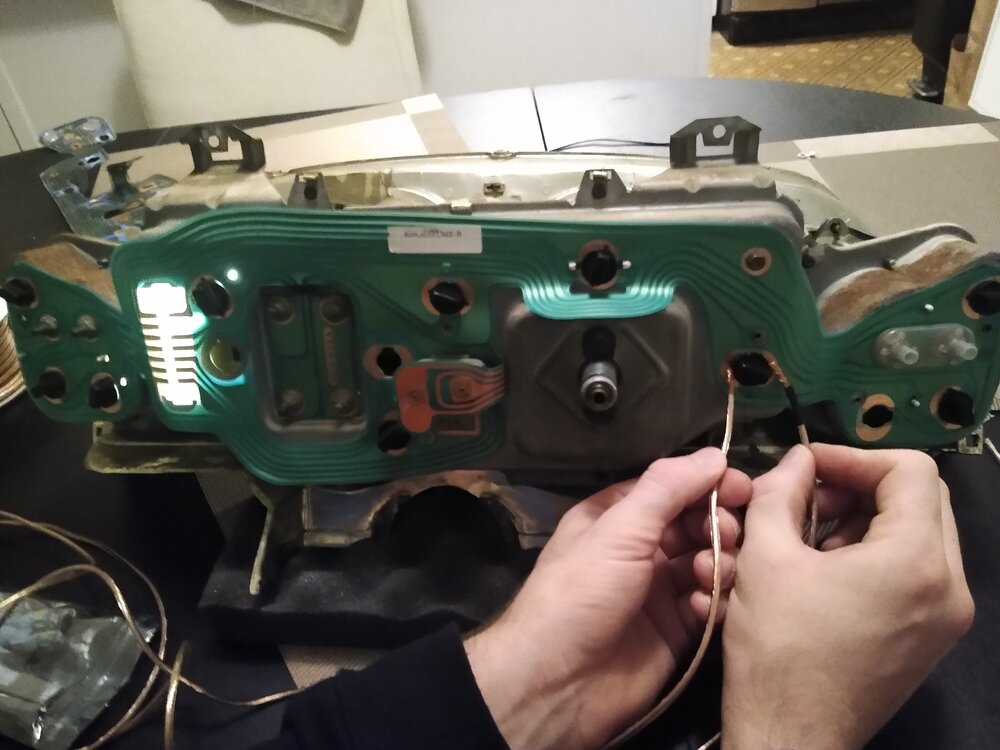
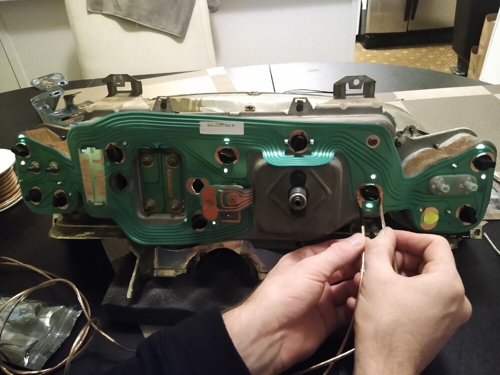
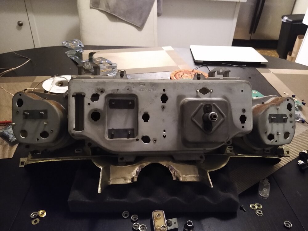
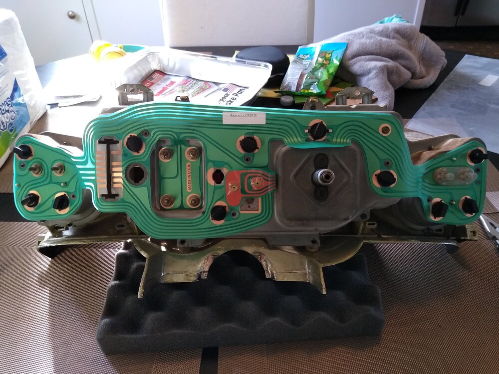
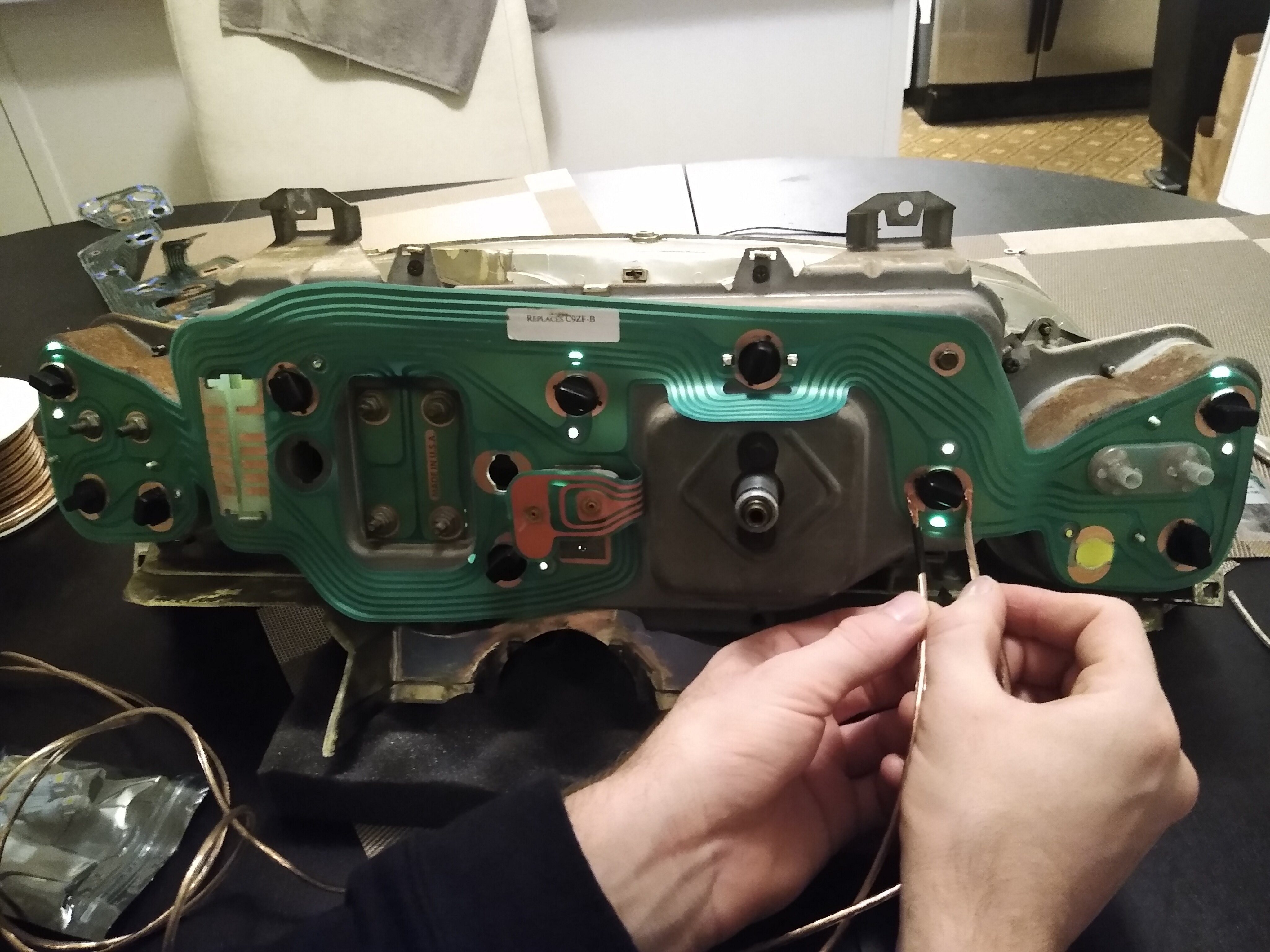
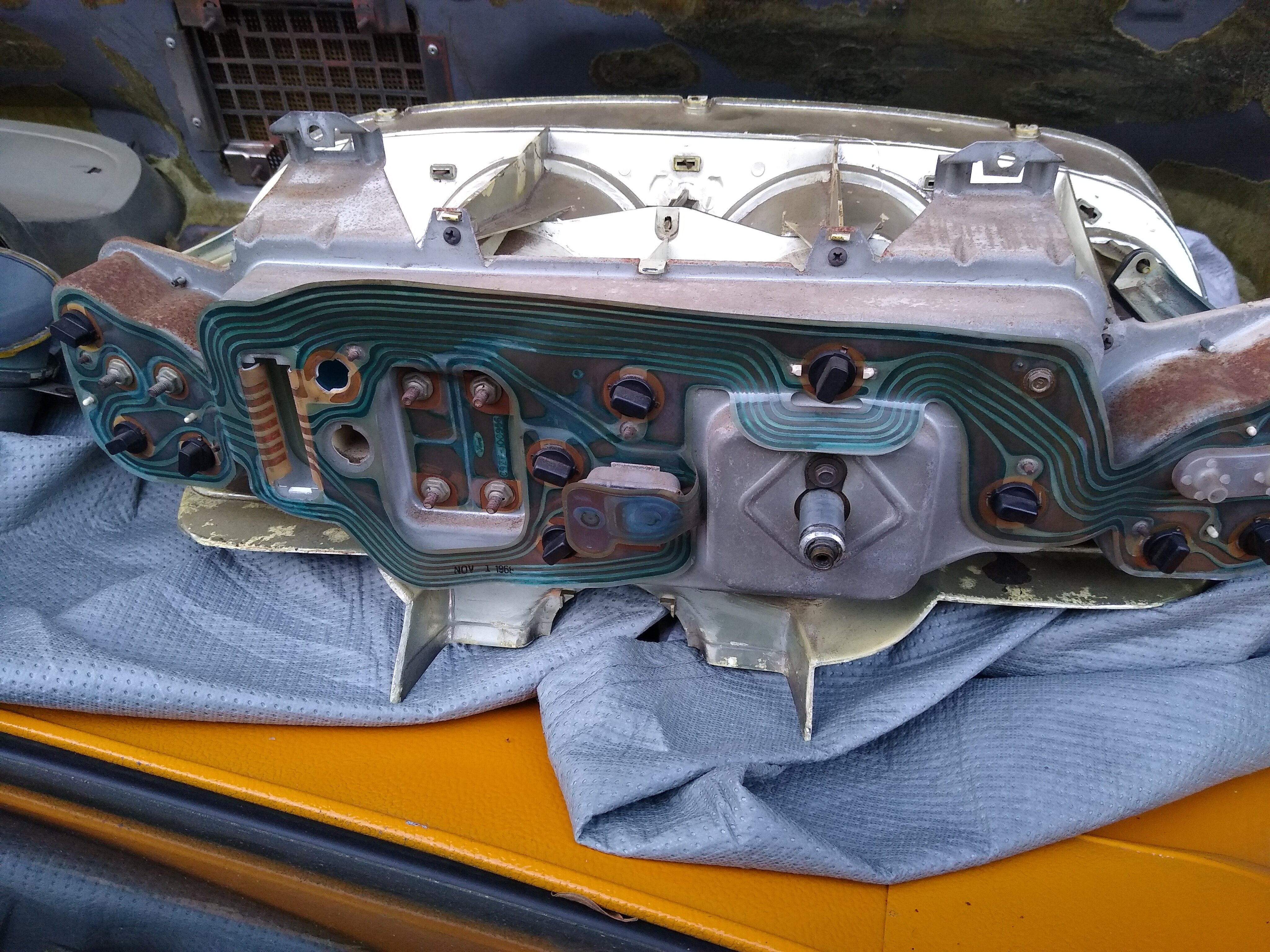
I recently decided to re-do my 1969 Gauge Cluster lights (no-tac). I had installed LED lights years ago, and, overtime, I had a few lights that had spotty and intermittent connections and the rattle of the engine combined with LA streets would turn them on and off. Once I pulled the stock PCB (dated Nov 1968!) I saw that the gold/copper "ring" for several of the light sockets were quite worn down and likely the culprit of my one or two flickering lights. ** To clarify, all dash lights work - just one or two goes out occasionally, but a *tap tap* to the cluster will illuminate them again**.
I figured a CJPony parts PCB (printed circuit board) would be a nice upgrade and peace of mind for night driving, but, to my surprise, after the install most of the lights stopped working all together! This prompted a thorough check of all connections with a multimeter, and I could find no break in the circuit on the CJPony PCB or the old PCB. I checked my wiring harness, fuse box, and tested that the wiring harness connector is receiving 12V - all good.
The only variable that changed is the new PCB, which I promptly took off and re-installed the old one. Then, my well-intentioned, but electrically intermediate brain, decided I will "improve" my light socket connections with a conductive material (aluminum foil) to make up for the worn connections. After taping foil (shiny-side only) around each socket connection and a quick check with the multimeter, I verified all circuits were still operational, and I re-re-installed the old PCB into the car. Unfortunately, my aluminum trick was only partially successful, and I still had some bulbs stay dark and some flicker with movement of the cluster.
MY QUESTION(s): Any thoughts/ideas as to why the CJPony PCB barely worked at all? Also, has anyone ever "re-invigorated" the light socket connections with success? Perhaps electrical grease or polishing?
For an "incandescent" look, I am using these LED bulbs without any colored diffusers, all of which have been tested and proven to work.
Pictures of the old, new, and "improved" old PCB. drive-download-20201127T031547Z-001.zip

-
Awesome, thanks!
-
Hey guys, my coupe is getting exhaust today, so I can't take a photo, but I'm hoping somebody will recognize my question about the fuel cap assembly on a coupe.
Fuel cap fasteners. There's a metal ring with a threaded stud (maybe 3/16?). Seems reasonable that it goes through one of the holes and a nut holds it on. Also, there are a number of other hole forming a circle that I assume are supposed to fasten the filler next to the taillight panel. Finally, wondering if there's supposed to be a gasket between the filler neck and the panel.
In bullet form:
- The thread size of the bolt on the gas cap retainer wire?
- What hardware to fasten the filler neck to the taillight panel?
- Any gasket necessary between filler neck and sheet metal
The car has been disassembled for so long...I've obviously lost some hardware and, more importantly, the memory of how it goes together.
A photo of somebody's stock cap assembly (cap unscrewed and dangling) would go a LONG way for me.
Thanks!
Tom
-
Hey guys, my apologies if my explanations are ambiguous as I'm not entirely savvy on this stuff yet. For what it's worth, I have no idea if my 351W block was decked. The PO said it was stock, but it was a craigslist deal and you never know. I never did have it examined nor do I know how to confirm. The aftermarket GT-40 clone, Chinese manufactured, heads I got at a speed shop on eBay. As I may have mentioned, that seller gets horrible reviews on Yelp for his engine builds, but nobody seems to have maligned the heads themselves.
My original Edelbrock Performer was an unknown quantity as well. It fit great on the original block with the cast iron heads (at least visually) as it was a running motor (again according to the PO).
When I said the "rails of the manifold", what I meant was the top of the sides of the manifold did not adequately cover the top of the ports on the heads, essentially exposing a tiny amount to the atmosphere. :) This obviously didn't go well when I got it running for breakin. My measurements revealed that the ports on the aluminum heads were "situated higher" off the deck than the cast iron heads (that's where .2" came in). The Performer was never going to cover this gap w/out some kind of serious machining.
Fate stepped in and my friend had a Weiand Stealth that was new (if not dirty). I've since installed that and -- yesterday -- re-fired up the motor. Huzzah! As of this moment, I can report initial success. I need to do some tuning today (timing, idle-mixture, float-adjustment, etc.) but the motor actually idled yesterday, so that's an indication that my vacuum issues are resolved.
When I called Weiand (Holley) tech support, they said the Stealth was just manufactured "taller" than the Edelbrock and they just happened to work better with the GT40 style heads. I took it as a design-consequence, not a design decision.
Anywho, I'm super grateful for the help here. I think I'm a big step closer to a driver. To 1969_Mach, I did take the time to remove the lifters, inspect, and re-install with assembly lube. Same for pushrods and rockers. Re-adjusted the rockers carefully as well. I lost a number of hours to my original bone-headed mistake of not looking hard at the fit of the Performer during original assembly, but that lesson is now hard-learned.
Tom
-
Thanks guys. I have a little gizmo to rotate the oil pump shaft. I'll see if I can get it "nuts on" again tomorrow.
-
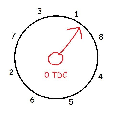
Hi guys, wondering if this is the best I can do when installing the diz. The crank is at 0 TDC and I can never seem to get the rotor to line up with spark plug #1. Obviously, the rotor rotates backwards when dropping in the gear, but no matter how I seem to set up the thing, the rotor is either past #1 or ahead of #1 (like shown in the picture). Is this "close enough" that can be fine-tuned with rotating the diz after the fact?
My brain tells me #1 should fire around 10 degrees BEFORE TDC so I would think the rotor should be slightly PAST #1 when installed at 0 TDC. Wondering if I'm explaining that well.
To simplify, what side of #1 on the distributor should I err on when I'm installing the diz since it never seems to want to drop exactly in. Here is a diagram of what I have right now.
Thanks!
Tom
-
I'd answer it like this: the top rail of the old intake sat literally below the top of the ports on the heads with no gasket at the end seals. The Stealth sits about 1/4" higher than the Edelbrock in the valley and covers the ports correctly. It took me a long time to realize this, but when I mocked up the Edelbrock with my new gasket, I realized it. I think these Chinese manufactured heads are the culprit. When I carefully measured the top of the port from the bottom of the head (where it meets the block), the aluminum heads were .2" higher than the cast iron. That plus the low-slung manifold created a no-fit situation.
I was concerned that a beat of RTV at the end seals was not going to "raise" the manifold high enough. The Stealth doesn't have this issue. So I'm ready to say that my Edelbrock just couldn't possibly work with these heads.
-
I think it might be kismet! A friend of mine came over today to take a look at my stalled project. He's a chevy guy (as many are). When I told my story of woe about the Performer 351, he casually mentioned he had a Ford intake in his garage that he was going to sell for a friend who has given up on wrenching. We went over and damn if it wasn't a Stealth 8023. Never been installed. Dirty and in need of cleaning. We test fit it (after cleaning it up) and it was perfect!
He asked for $50 but I gave him $100 as I was *this close* to paying $256 (plus CA tax) for it today from Holley. I'll sell the Edelbrock that came with my block and hope to break as even as possible.
Super happy with the manifold. Fits my air cleaner setup and the hood closes!
Look for better stories from me in the days ahead as I think I've solved my big vacuum crisis.
Good weekend, all.
Tom
-
I'm starting to answer my own questions...maybe that's a sign of growth? I doubt it.
Careful measurement reveals that the tops of the ports of my GT-40 Chi-Clone heads are .2" higher than the cast iron heads. This manifold obviously fit great with stock heads.
So, it seems that my original vacuum leak was probably not a result of poorly installed or poorly chosen gaskets, but a result of myopically installing an intake w/out any regard to its fit with this setup.
Did somebody recommend the Weiand Stealth? I am thinking about calling the manufacturer to see if it accommodates this much taller head port.
Still, your insights are appreciated.
-
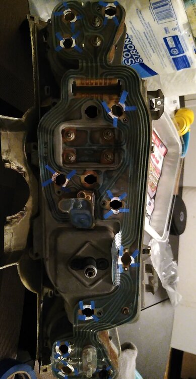
Hey guys, am mocking up the intake with the Fel-Pro 1250S-3 steel core gasket that was recommended. I'm starting to thing that something is off with the geometry of my block, heads, manifold, whatever. When I mock up the manifold with the side rail gaskets in place, but no front/rear gaskets, the manifold sits "very low" and the top of the rail doesn't even cover the top of my ports on my heads. This can't be good. :)
When I measure the gap between the manifold and the front/rear of the block, I get 1/16th in the front and 3/32" in the rear, so not a very big gap at all.
I then mocked it up by putting the cork front/rear gaskets in place and the manifold obviously set up a bit higher, but it now just barely covers the blue outline on the gasket around the intake ports. This is the bit that creates the seal. I have a picture of this with the suspected port areas outlined in blue.
I'm starting to believe that, yes, I may have had the wrong gasket set initially, but am also now wondering if the basic geometry of my setup is bogus and that something may have been modified, the heads not sized correctly, etc. This is all coming from a newbie, so please forgive the poorly constructed thoughts.
I don't have another manifold lying about, but I am willing to do whatever to measure, verify, etc.
As important, I don't plan on using the cork gaskets in the final install, which has be concerned that my height problem will be even worse since the RTV will "crush" much more readily than the cork.
Thoughts and ideas are very welcome.
Tom

-
-
At the moment, the gasket is installed, so I can't say with 100% certainty, but it came with my 351W gasket kit from Summit. As near as I can tell from the Summit page, the number is 8548PT-2.
My question is more generic: is it considered bad practice to use the single shim style head gasket with aluminum heads. It's hard searching for a distinct answer. Folks talk about layered gaskets and other stuff due to the differences between alum and cast iron. Just trying to get out in front of a potential bad choice while I'm taking everything apart again.
-
Hey guys, if you've been following, I managed to create a pretty bad situation with a poor choice of intake manifold gasket on my 351W rebuild. Now, my attention turns to the head gaskets I used on my cast iron block and GT-40 clone aluminum heads. I used the regular single shim style gasket that came with my Fel-Pro kit. I've got the intake off and just about to go through the valve train (again) after re-lubing everything, and am pausing for some sanity.
Are there strong opinions on there about a properly installed single-shim style vs. something else?
I've got no reasons to suspect a leak of any kind, but I would prefer not to have to regret that decision later.
Oh, and is there conventional wisdom on re-torquing the heads after a breakin cycle? If so, does that mean loosening them, and then re-torquing? It seems weird to just stick a torque wrench on there and expect it to move...seems like the static friction of the bolt would make a false positive. Thoughts?
Thanks as always.
Tom
-
Well, some dang good news for once. I pulled the lifters one by one and inspected for any signs of wear. Happily, there are as smooth as the proverbial baby's butt, so I don't think I did any detectable damage to the motor during that 40 seconds of running with coolant in the oil. Put them all back in the same hole.
My Fel-Pro 1250S-3 gasket is on its way and I'll clean up the block, manifold, and heads before re-installing.
I'm going to do the "dry fit" test as Barnett suggested to see how much gap I have in the front/back. I remember thinking originally "that's a big gap", but I didn't realize then that a 1/4" was normal. I was expecting a pretty tight fit, but I'm educated now. :)
I'll keep you posted on the progress, but meanwhile, please accept my sincere thanks. I learn so much here and I don't give back a damn thing. I hope to change that.
Tom
-
4 minutes ago, barnett468 said:Take the lifters out and look at the bottom. They should be perfectly smooth, if they are scored at all the cam is likely dead. Look at the cam as well. Put the same lifter back in the same hole it came out of.
I'm seriously afraid to find out. I think I'll do that first thing tomorrow. Why ruin a Sunday evening. :)
-
12 minutes ago, barnett468 said:No, it has to match the largest port. If the intake ports are larger than the head, it must match the intake port.
The better gasket by far is the felpro steel core.
Roger that. The ports on my head are larger than my intake, so I just made a bogus assumption that it's always that way. Again, I learn something every time.


C4 tranny year compatibility with 69 coupe
in 1969-70 Technical Forum
Posted · Report reply
Interesting...no mods at all? Bell fit in the cowel? Same drive shaft, x-member, blah blah blah? I suppose I'll keep that in mind if my rebuild fails me.
Thanks.