

latoracing
-
Content Count
1,077 -
Joined
-
Last visited
-
Days Won
47
Posts posted by latoracing
-
-
2 hours ago, grendi said:245-55-15 does not exist,
It does exist https://www.jegs.com/i/M-H/676/ROD-29/10002/-1 in a drag radial. (which shouldn't be used for steering axle applications). Just attempting to convey an idea of bulge and relative side wall height from a visual standpoint. As a "normal" off the shelf, common size tire, I didn't go and see if it did exist.
-
On stretched (dented) areas, a shrinker disc will do wonders, and you can get great results in no time. Try it out on your goose egg on your fender to practice, I bet you can repair it as well.
Try using a thin piece of cloth between your hand and the panel to help you feel the high and low areas. Don't use your fingers but rather the palm of your hand. You will get to where you can feel these imperfections and the cloth will not be need. Worked for me...
-
Your rear tire height is right at 28", quite tall. A 245 tire (depending on the manufacturer) would be 9.646" wide (245 / 25.4 = 9.6456"). Section width and sidewall height will help with the bulge of the side wall and overall height. I don't think it would look right with a 28" tall tire on the front, more like 26". A 245-55-15 would be 25.6106" tall (+/- per manufacturer) without much bulge, but might be similar to the rear on a 7" wide rim (I'm guessing here). The 1" difference in width (275 = 10.8268" vs 245 = 9.6456") would need to be accounted for.
Me, I'd do a 10" rim out back with the 245's on an 8" rim on the front.
-
Nice work.
That looks like a fun part to tool up for a stamping opperation.
-
The driver's side is a different story. Previous damage have distorted the panel, there's a bunch of stuff to fix. I was working on this side before fixing the tail light panel and the passenger side marker light delete. I do have access to the inside of this side so I can kinda use hammers to stretch welds and smooth out the other damages. This side received the same shape filler part, but it took a bunch of pounding to get the quarter to line up to the patch. It's getting there but it will take a while to get it to resemble the passenger side.
-
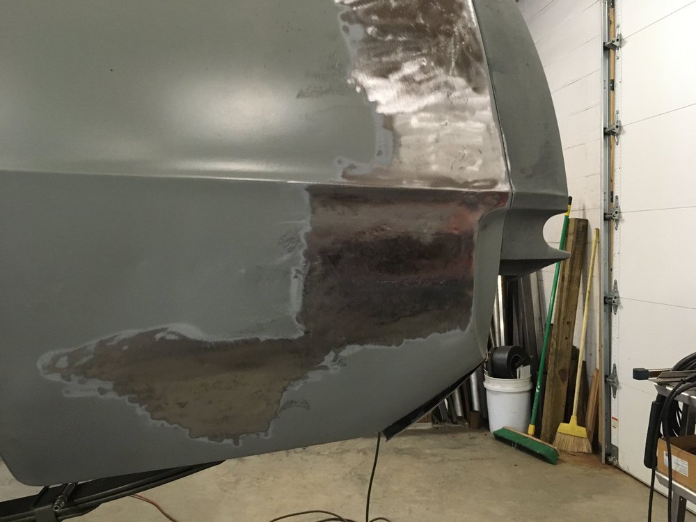
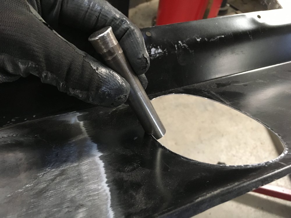
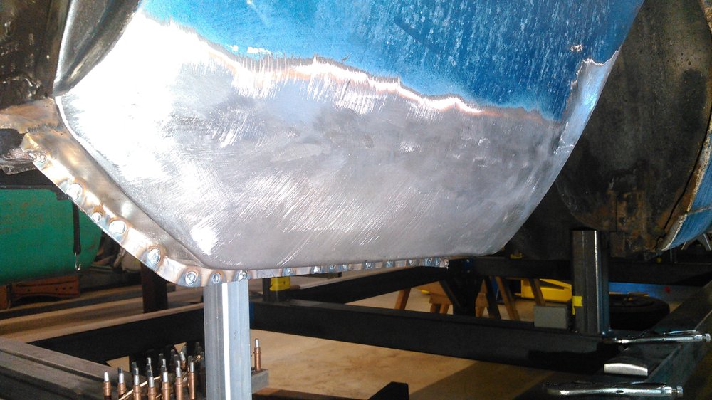
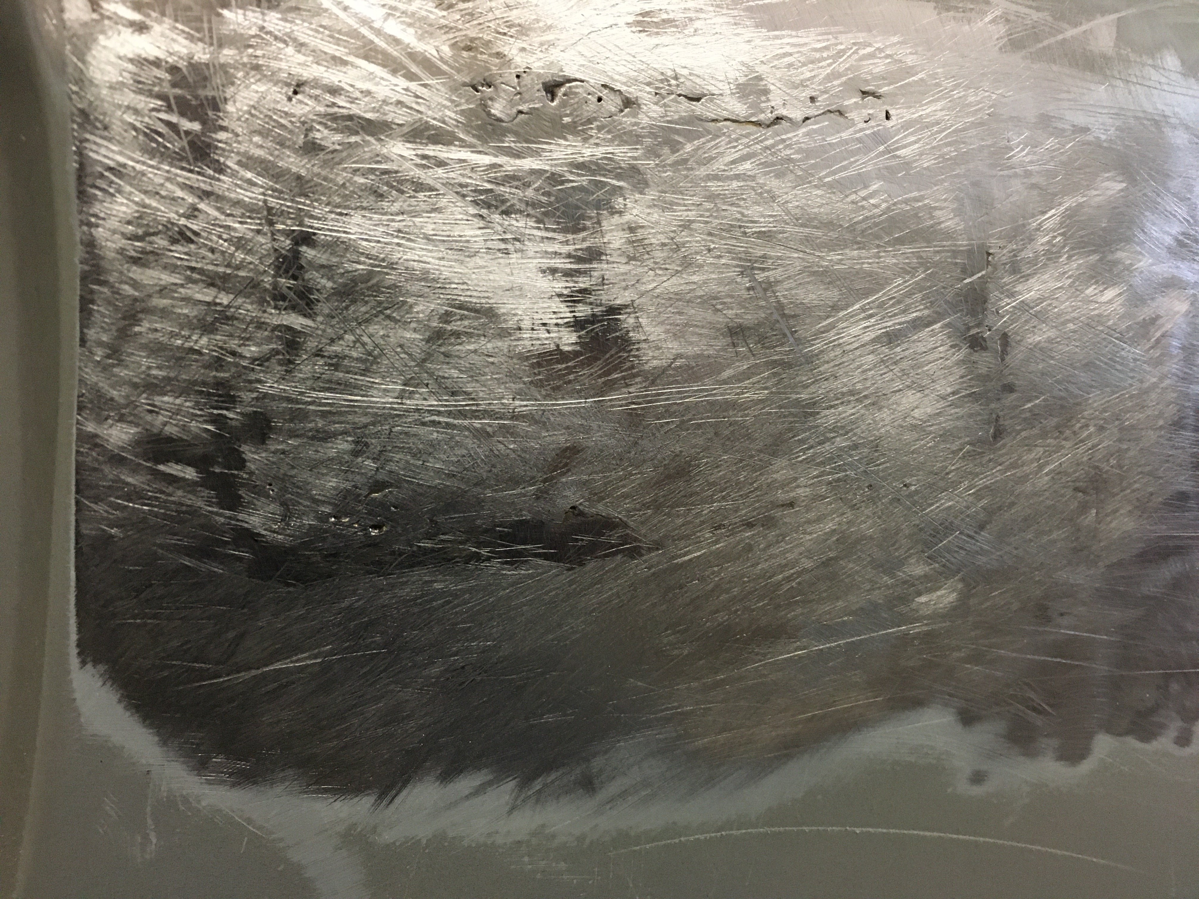
I wanted to show a little bit of the metal finishing process, at least what the area looks like while finishing the welds and related distortion.
The "proud" profile of the weld is almost leveled to the panel surface with a 36 grit rollock disc. The 36 grit cuts really fast and does not introduce a lot of heat back into the panel. A 120 grit disc would also remove the weld tops, but will get really hot, we don't want that. Once the tops of the welds are knocked down a flat faced body hammer and the heal side of a body dolly are used to give shape back to the weld areas. As the welds cool, they shrink, so they have to be stretched back out. It takes a little bit to get the shape in the general area then I switch to a slapper with the same dolly to spread out the blows. I use the stripper disc to go over the area to give contrast to the high and low spots. I meant to get some blue layout dye to really show this. At this point I use nothing other than hand files to level the metal. I start with a bastard cross cut flat file to highlight the areas to focus on.
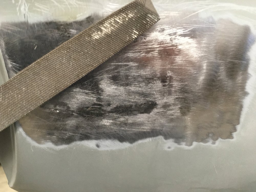
Paying attention to the welds, as they are the offending material that needs to be removed, and bringing up the low spots, the slapper and dolly are used to continue to bring out the material. I cannot access the back side of the quarter with a hammer, that would be much easier. Lots and lots of light rapid hits and "block sanding" the area with the file the metal starts to look better.
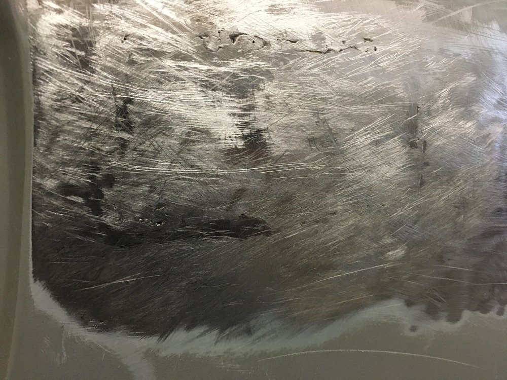
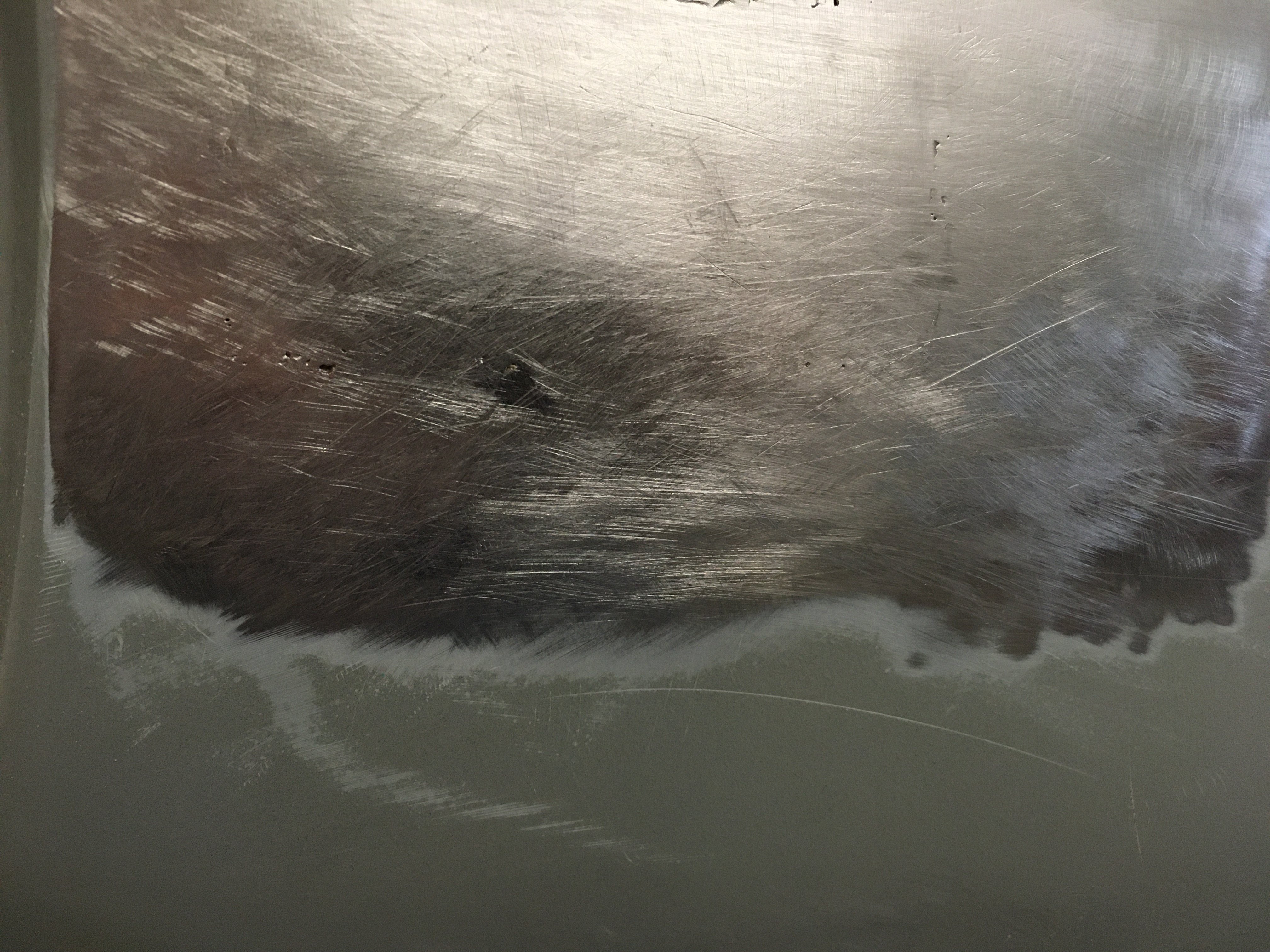
As the seams disappear, I move to the rear (left of the picture) to continue to get out the low spots. You can see the small divots or porosity in my welds from the paint contamination. They do not go all the way through, so I did leave these imperfections. More slapping and checking with the file I needed a reset on the finish to see lighter imperfections in the surface. Using the stripper disc again and switching to a mill file, the area was gone over again.
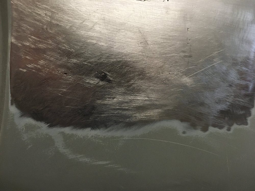
There is one little place (about the size of a pencil eraser) left to planish out in this picture. I can continue to perfect the surface towards the top, but these areas are so small, a skim coat of filler will be used anyway, so it will be left. You can get this entire surface like this using the same method. Start to finish on this fill in has taken 3 hours.
Back to welding up the other side...
-
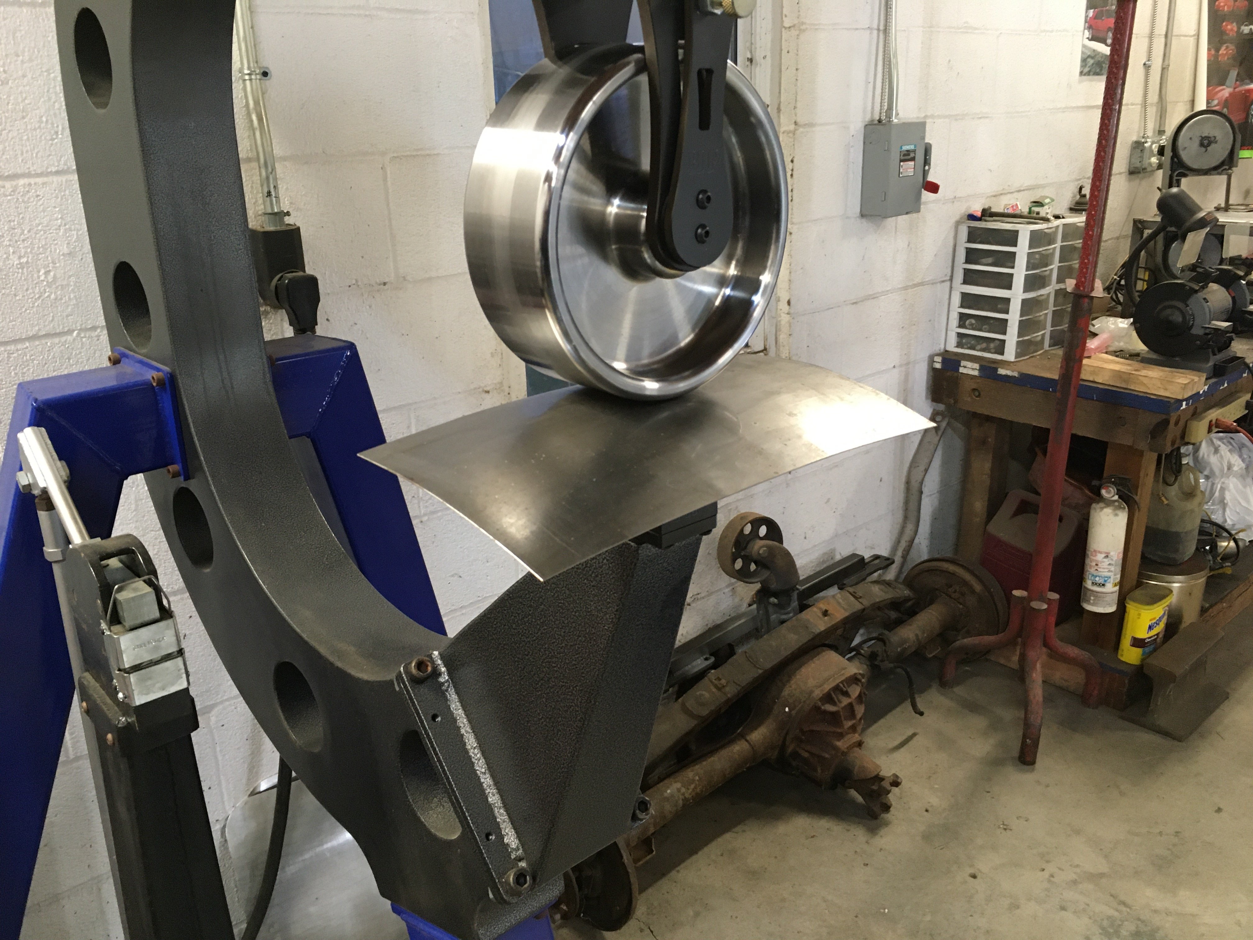
Getting to work on the marker light delete I needed some parts to fill-up the holes. A little 20ga scrap and a 8.5" radius lower anvil on the english wheel and the scrap was shaped to fit my templates. It took a couple of checks but it finally got to the shape I was looking for.


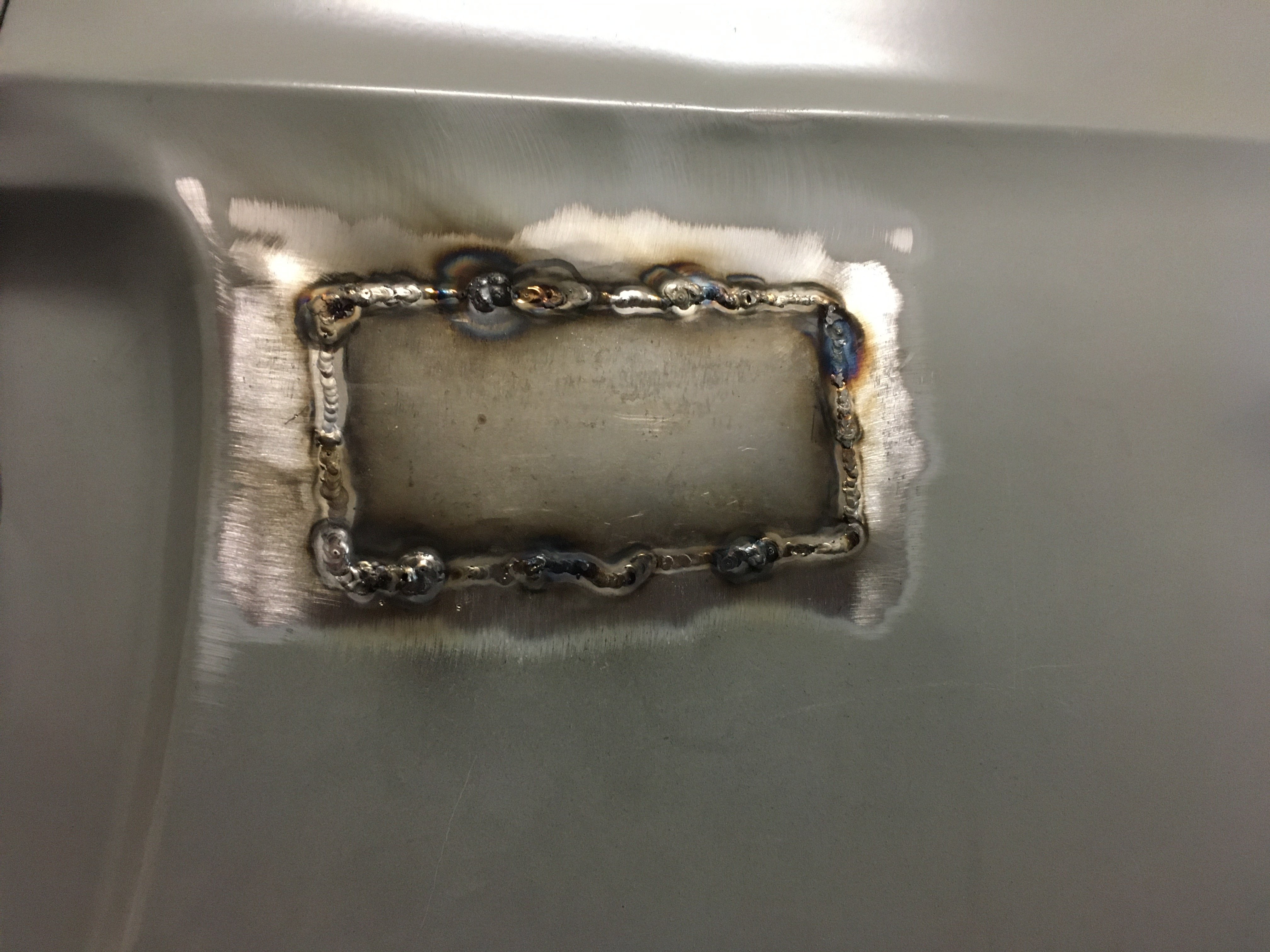
Cutting this formed sheet in half I put the part in the trunk holding it on the back side of the marker light hole and scribed the outline. A little trimming and a little final shaping the passenger side was tack welded in place and fully welded little by little.

I accomplished the weld with my TIG, it doesn't like paint or dirt so it got a couple of holes in the weld, which were filled up. I'm not going for a beautifully formed weld but rather for a higher crown quite cool filler application. I used .030" mild steel MIG wire and a 1/16" tungsten set on 55 amps DC- if anyone wants to know.I have sanded off the welds in order to planish out the area and get it looking like it should. The driver's side shouldn't take long either.
SWPruett and Grabber70Mach reacted to this -
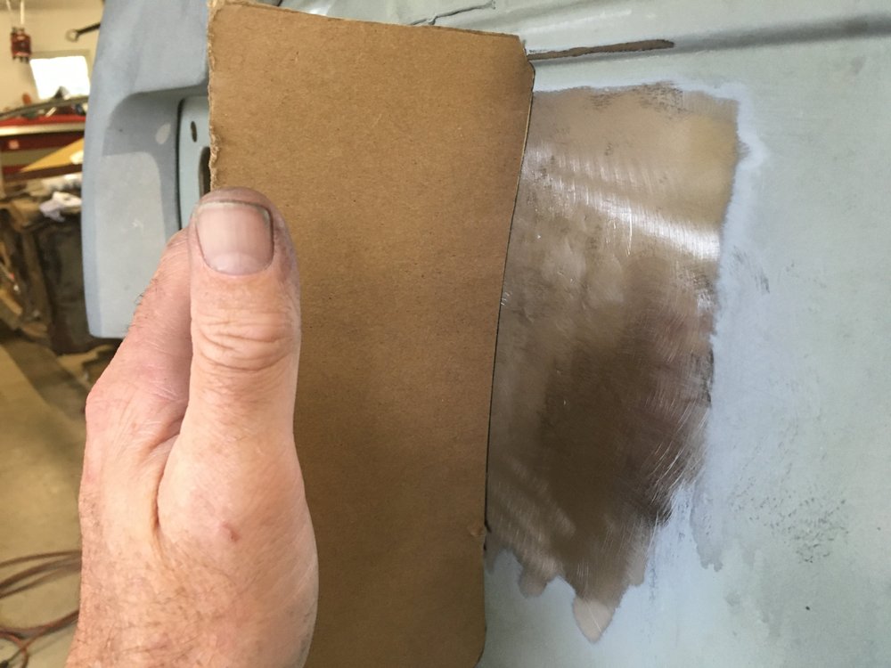
This divot took about a hour to repair, the disc is good, but you have to take your time and feel what the metal is doing. Smooth dents are fairly easy, crunchy dents (like this one) take a little more time. It doesn't turn the metal blue when you use it, like a torch does. You get a feel for how long to run the disc over the area and hope the soapy water seams when it hits the metal. You can let it cool naturally, but that takes a while. The metal will continue to shrink after you use the water. It's a neat tool. A little practice and you can get good results. I did not use any sand paper on this repair, just a piece of red scotch-brite pad to clean the wheel and to remove the residue from the panel.
Grabber70Mach and newstang reacted to this -
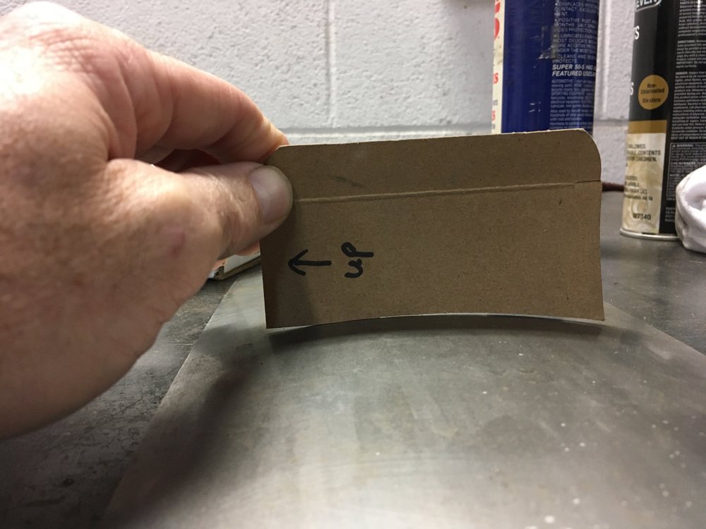
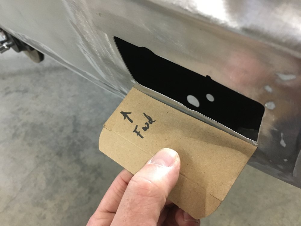
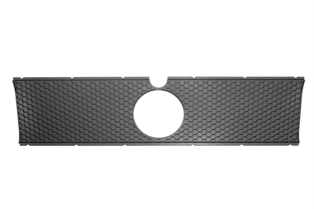
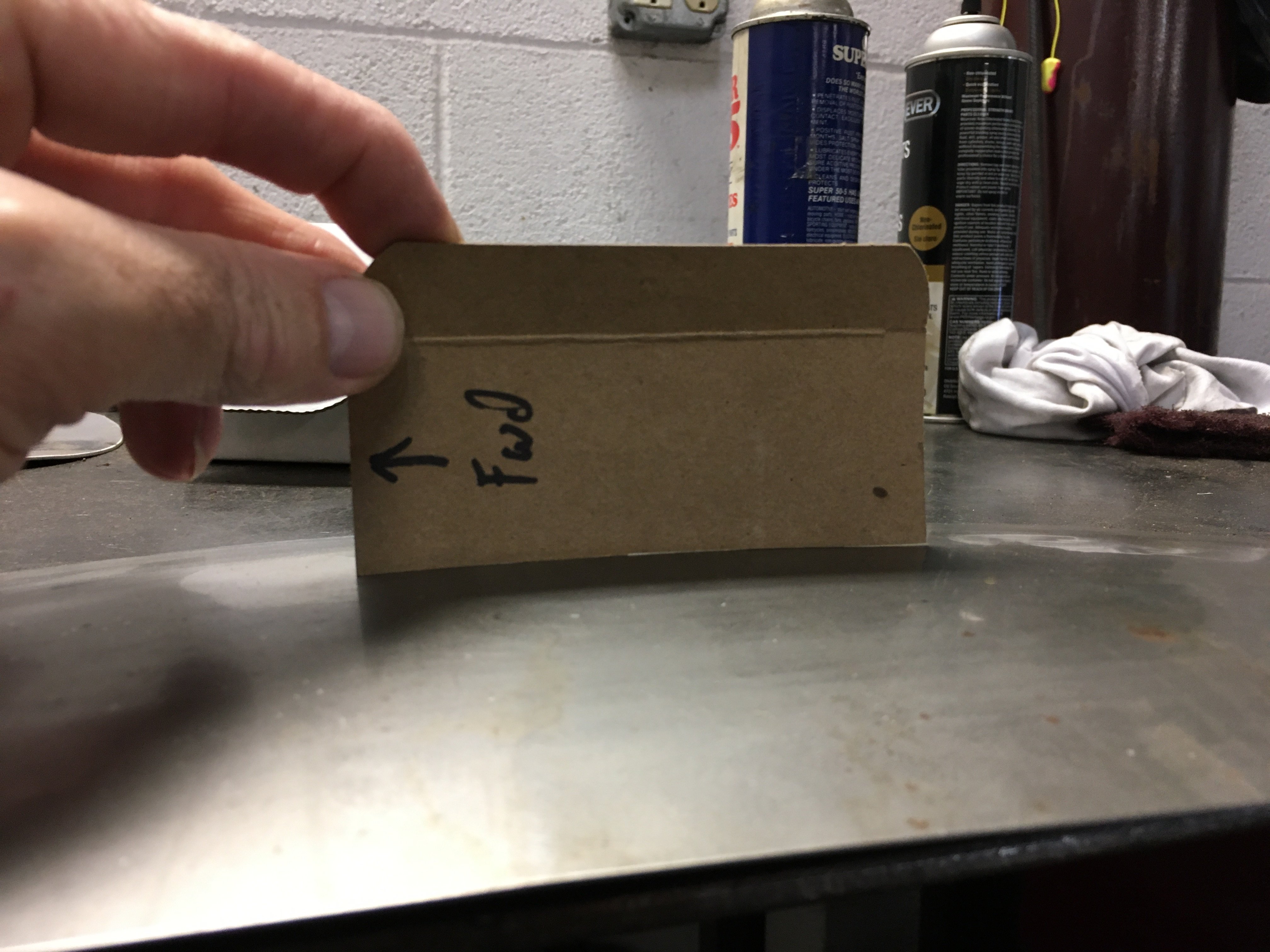
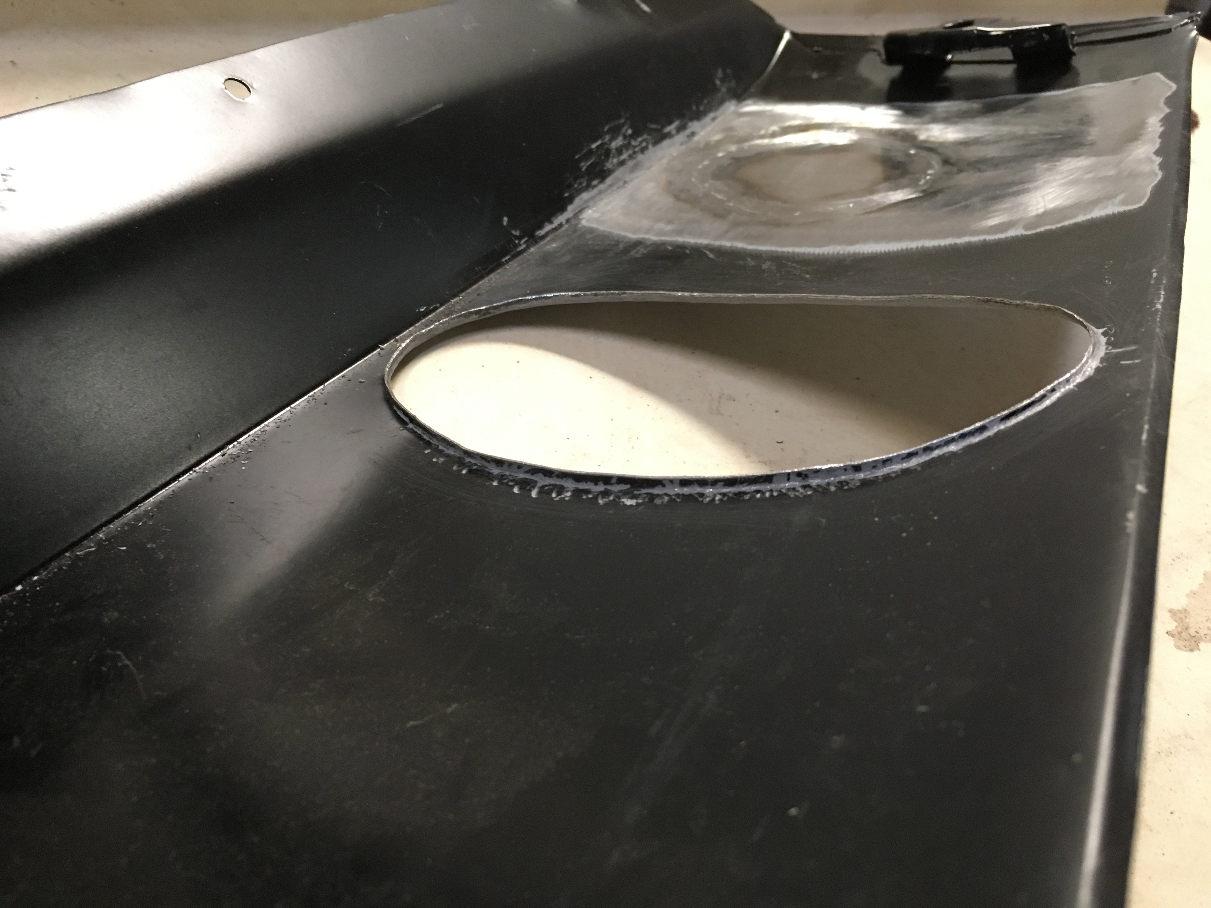
Time to get back to something funner, filling in the quarter marker lights. I can't just grab a piece of sheet metal and weld it in place, well, I could but Vic wouldn't be pleased with the results. I cut out some templates of the area for filler material shaping and to check the shape after everything is welded in place. The templates were of the passenger side quarter as the driver's side has some damage, which i'll get in shape before I install the patch.
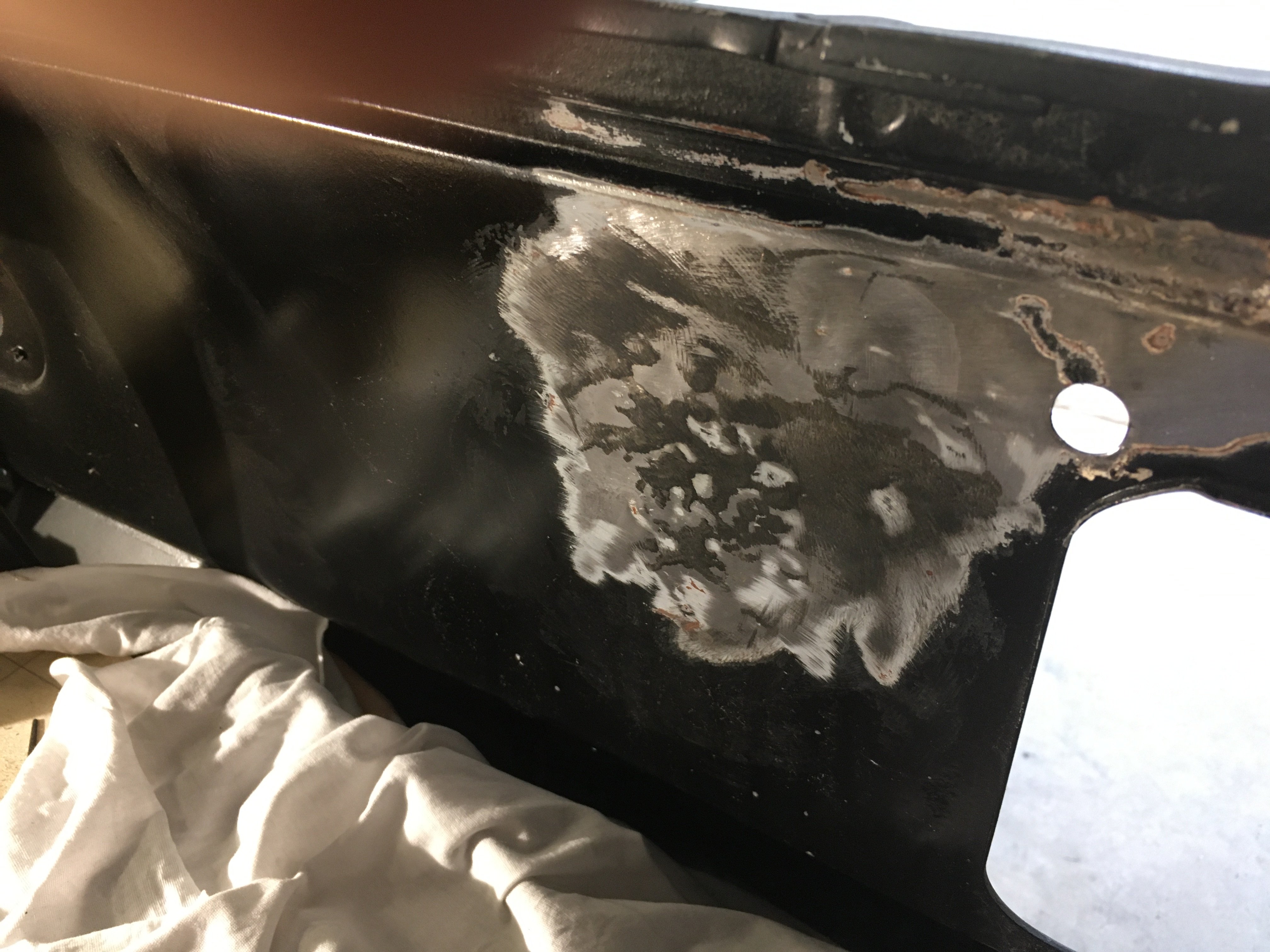
Using a orange stripper wheel revealed a bunch of previous "repairs" that were covered in filler. The tail light panel has a fairly good size goose egg shaped divot close to the tail light opening, its pretty bad. Might as well get that back in shape while I'm here. Cut out another template and checked the profile of the area, not good.
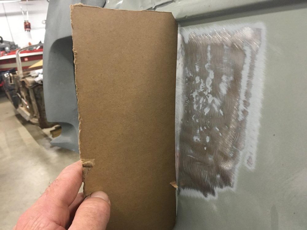
In order to fix these areas the paint had to come off on both sides, more orange striper disc time.

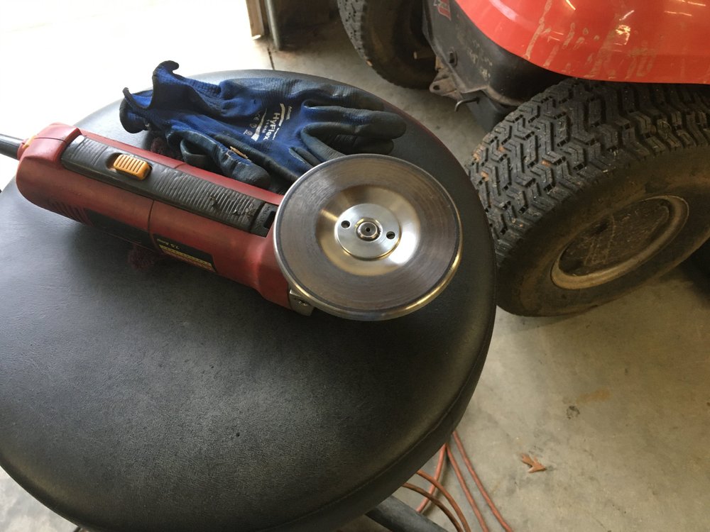
The upper section had been pushed in as well, so it was pulled and hammered back in to position. I have been using a shrinking disc for over a year on different issues, mainly self inflicted distortion when fabricating parts. It is nothing more than a stainless steel disc with a backing plate on my 4.5" grinder. It is not abrasive, but when you use it on the dented area (mainly on the inside of the trunk panel) a little soapy water helps lubricate it. Keeping the disc flat to the surface, as much as possible, you run it over the area with enough pressure to keep it on the part, no more. This heats the metal enough to quench it with the soapy water solution. Wipe off the excess water and repeat until the dent is gone.
A little work, some pulling by hand and a little hammer / dolly time it looks like this.
This area had a bad oil canning to it when you pushed on the panel. That is now gone and as you can see the shape is really nice. I have some more little areas to planish out but this could be shot with filler primer and blocked out. I like my shrinker disk
-
It looks better in person.
-
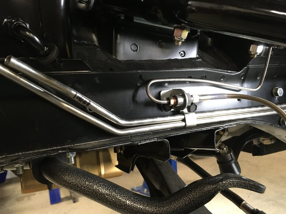
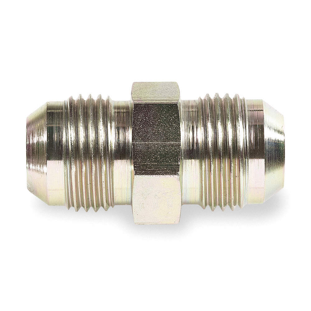
Having both ends of the line flared to 37* you can connect them with...
 Mach1 Driver reacted to this
 -
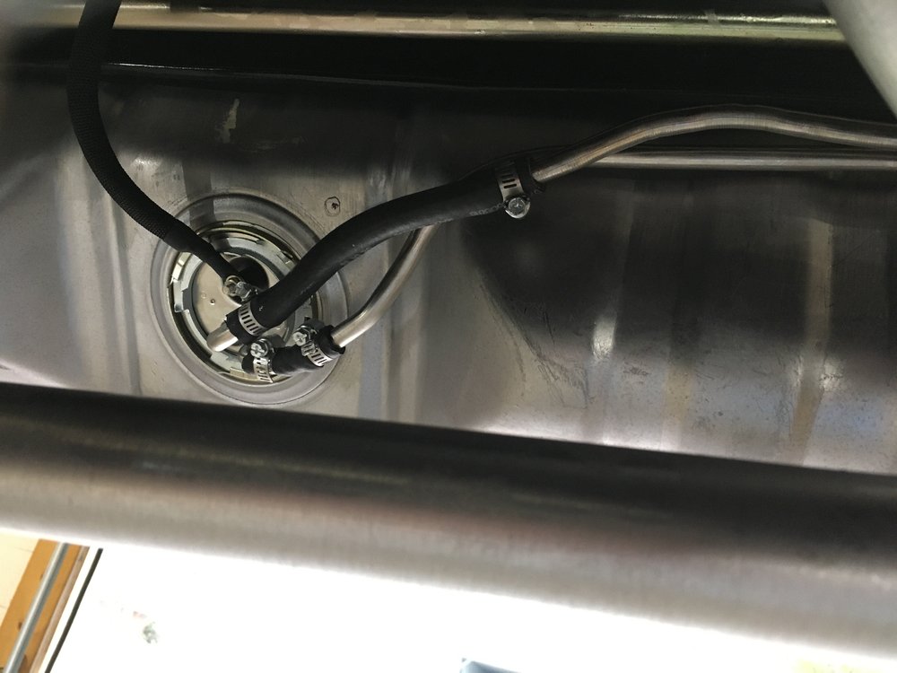
Vic is using a mechanical fuel pump to get the fuel to the EFI canister (in the engine bay) that ups the fuel pressure. Up to the pot, the fuel pressure is 6ish psi. I cut a few of the ends off the supplied lines for routing purposes and re bubble flared the lines. If this was an in-tank pump, I would have used AN flared fittings for all hard lines and EFI safe AN flex lines.
-
Bronco
in The Garage
Gotta love Lego's. Those look nice.
-
The kick panel patches turned out nice. Great job!
On your quarter patches, I would recommend buying the outer wheel house and chopping out the part you need. It can be formed, but you'll spend as much money on a piece of 20ga sheet metal. Having a basic shape that you can tweak to fit vs fabricating parts is easier (but not as much fun). The outer skin can be massaged into position as well. Keep your patch larger than your hole and trim to fit, much like the kick panel parts. I'm sure it will turn out nice as well.
-
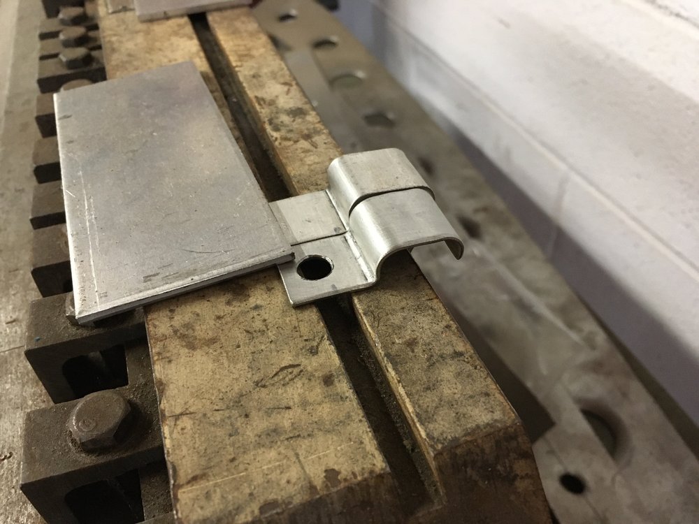
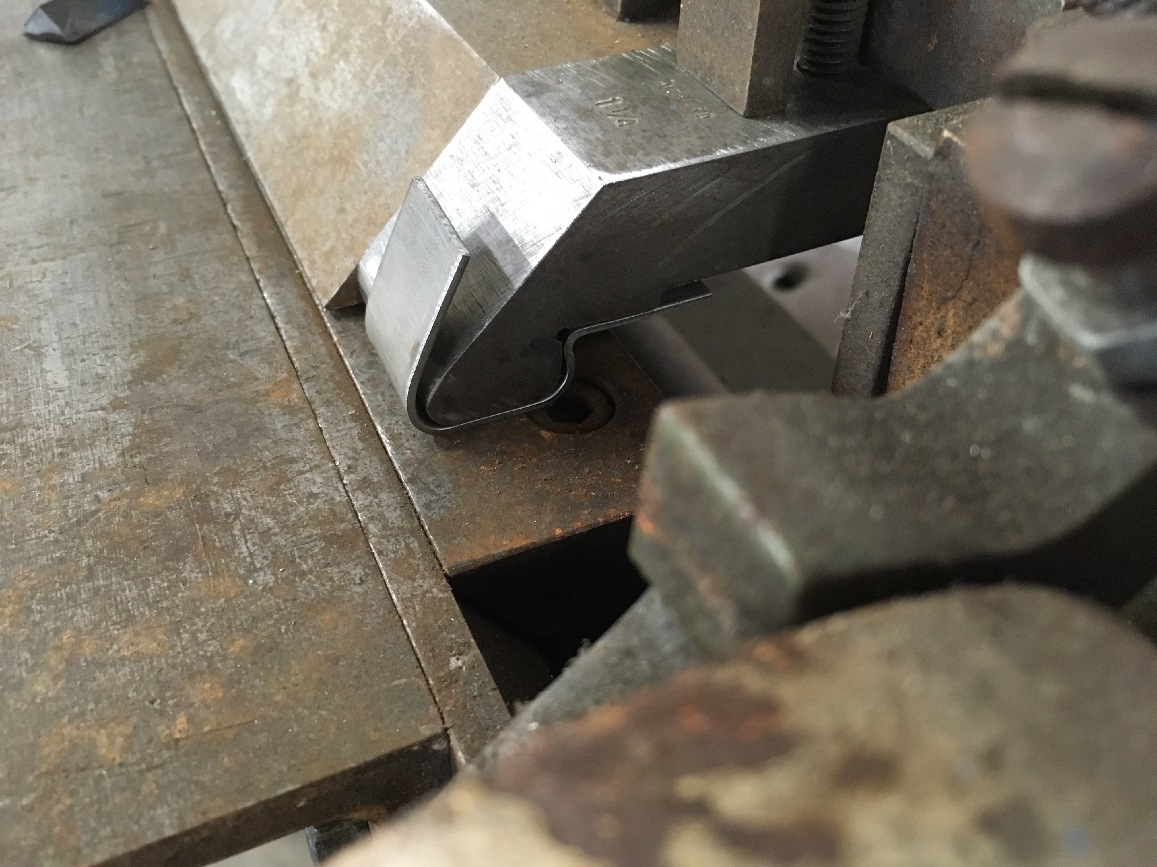
The material is 16ga 304 Stainless Steel cut into a 3/4" wide strip. I haven't measured any of this yet, but I get 3 clamps out of a 8" strip. Trimming is required on each piece.
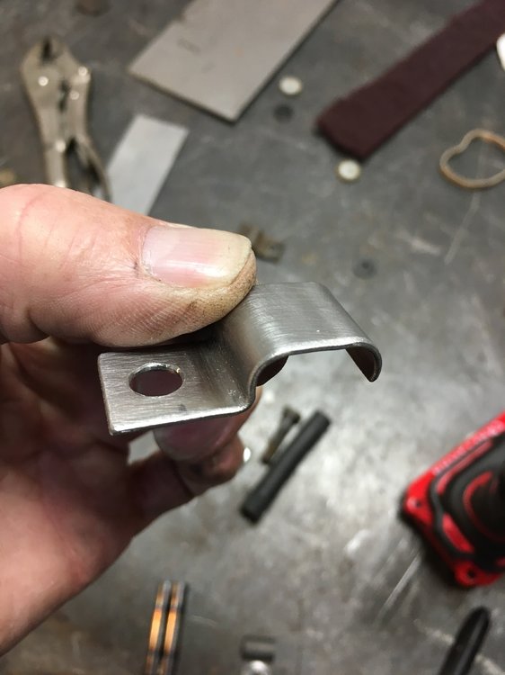
The first bracket I did was by eye from a 90 degree bend and step breaking the radius' on either side. The tooling was done with my porta-band saw and some files.It makes it nice since the bends are basically one motion, minus the 90 degree flange for the bolt. Its tricky to get it started (more eyeballing required) and once the flange and radius are formed it gets turned around and clamped back in place and the second bend is accomplished.
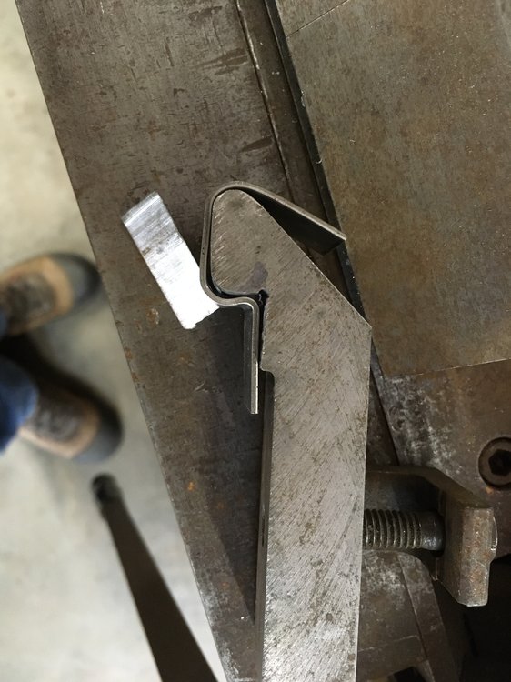
Comparing one of the "quick" tabs to the first attempt looks pretty close.
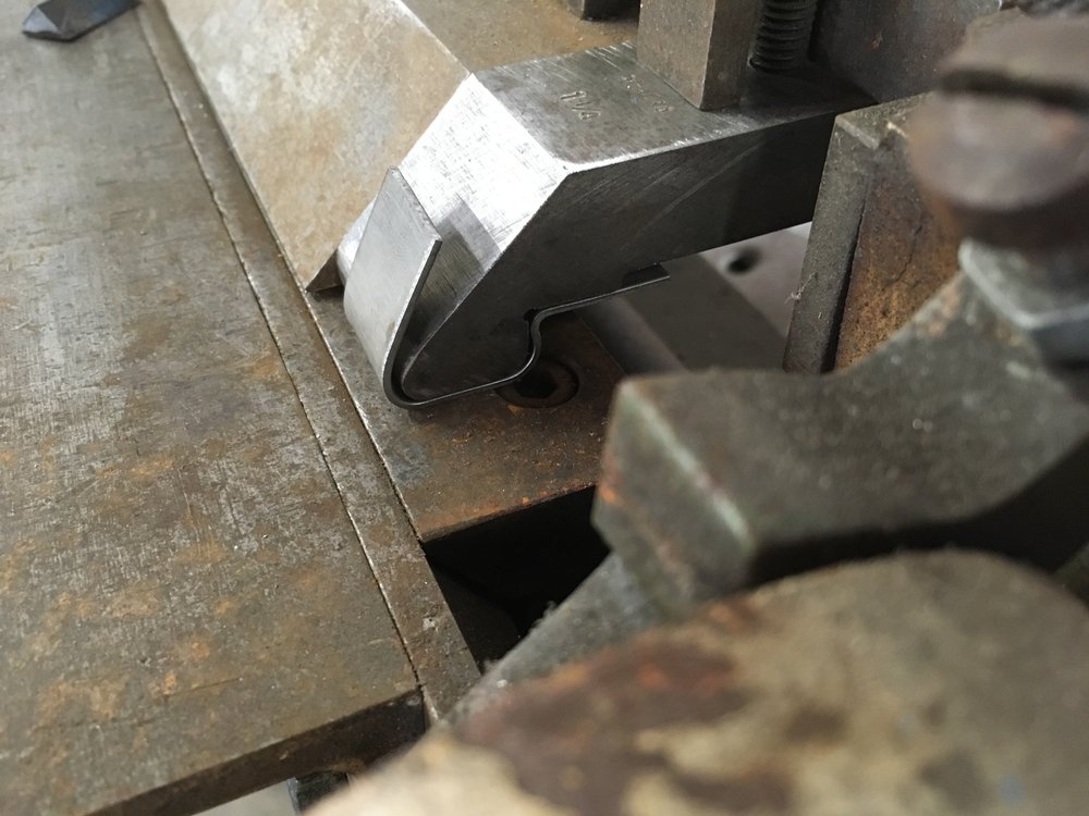
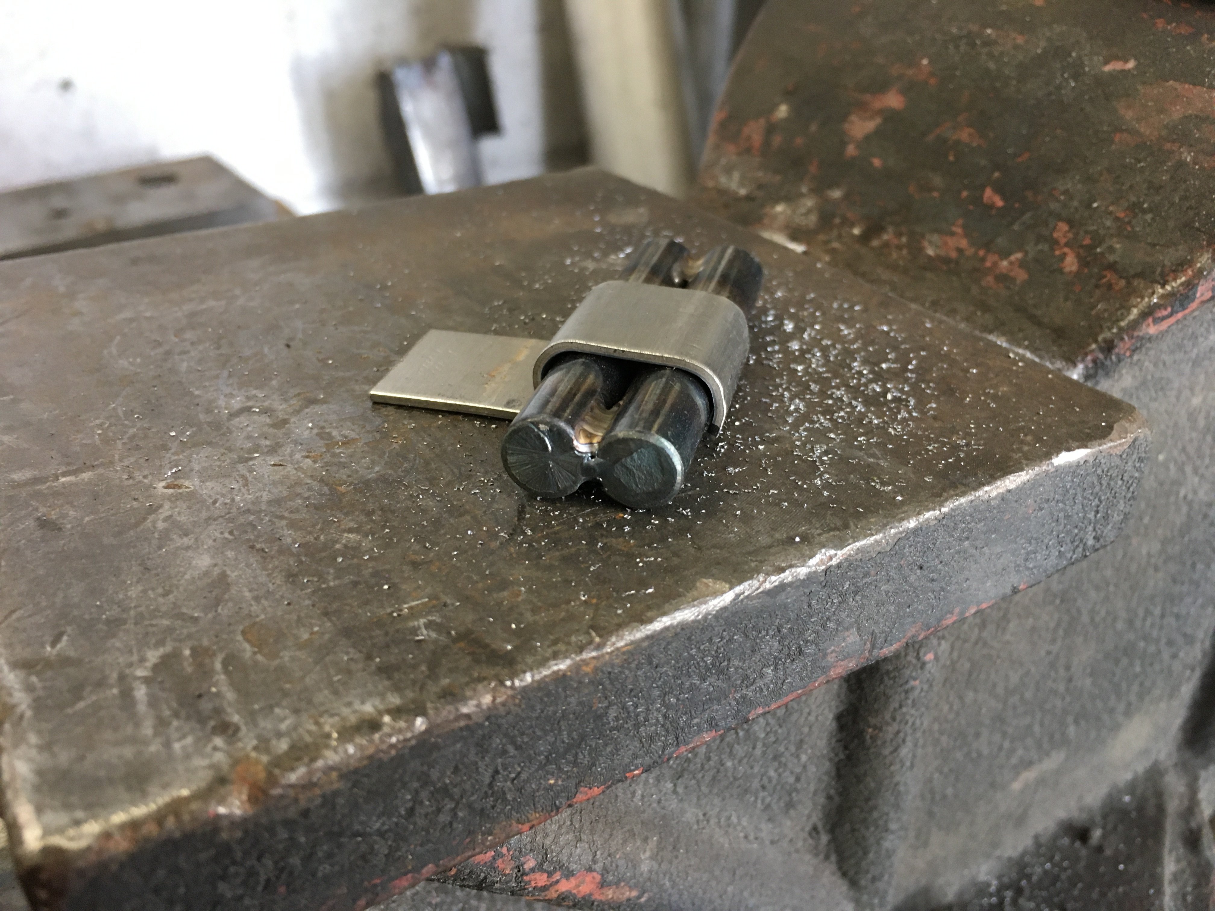
For these clamps to actually clamp they are adjusted with two welded together 3/8" 1018 solid rods I fixed up when I thought about building these. I place it in the vice and hammer the ends of the clamp tight to the rods. The clamp has to be slid out the side for it to come off, which will make sure the fuel lines will stay in place without moving. A little drilling and some de-burring is all that's left. Repeat as necessary
 Mach1 Driver reacted to this
 -
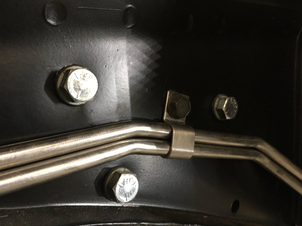
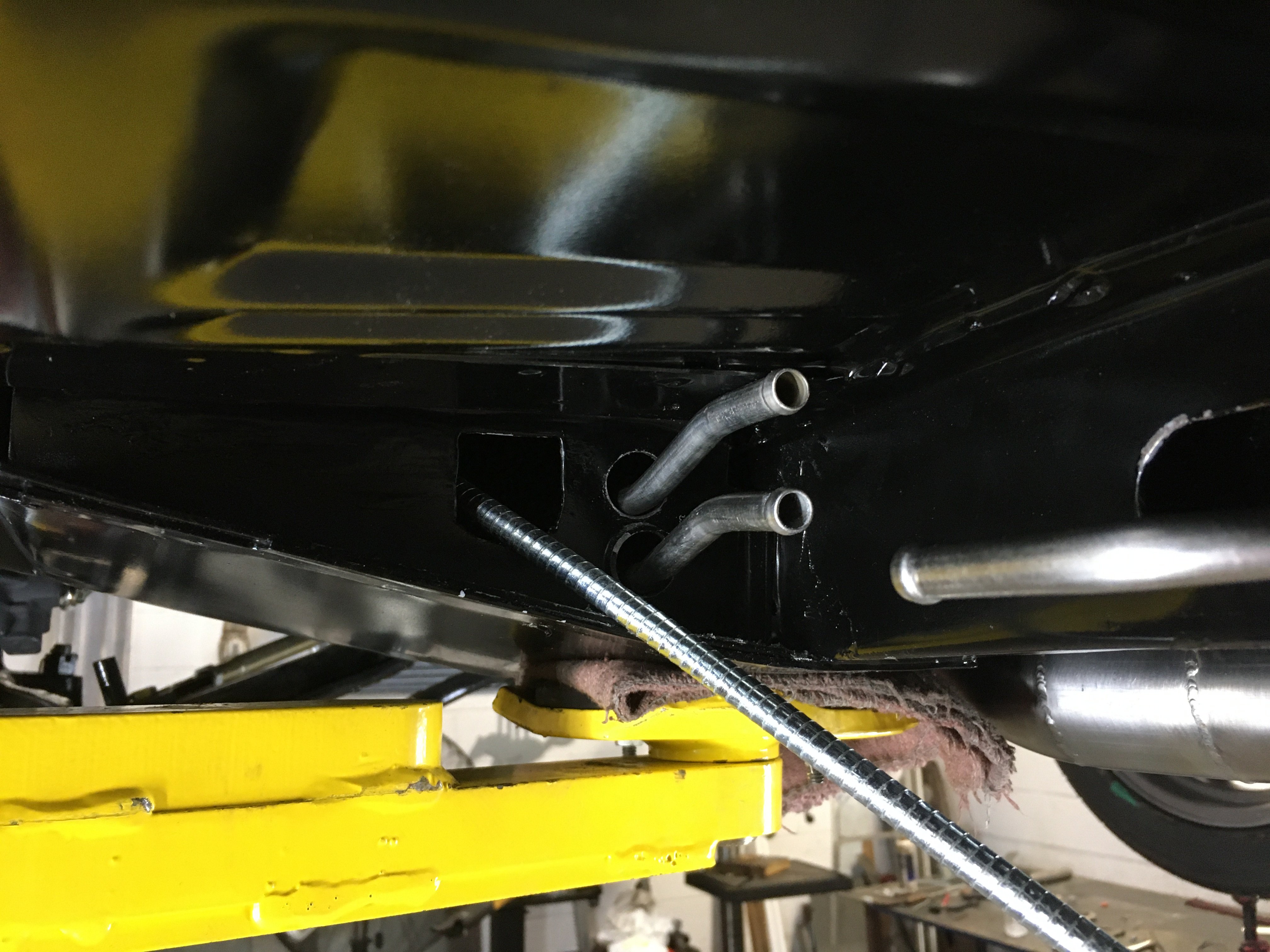
When you get to do tedious jobs, there isn't a lot to share that is exciting. With a couple of delays I'm finally able to get on with the return fuel line. I'm using a stock 3/8" stainless line for the return, which is going to look really good. I did some bend manipulation to the prebent tube and drilled a 3/4" hole in the back of the torque box for it to pass through. Both lines fit through the stock oval front hole, which took a little bit of time so both tubes are not bound tight.

Spent a while looking through the inter web to find some appropriate clamps, which I didn't find. The closest clamp I found was 1/4" and 3/8", no dual 3/8" clamps sooo....
A little tooling and creativity with some stainless sheet and we have clamps.
I have to cut and bubble flair the new tube for its attachment up front and get it all bolted down to stay.
-
I use to build and repair aircraft parts fabricated out of CF and composite laminates. I have been wanting to get back into this, but haven't had the equipment to do such. This video shows the use of prepreg material, which makes this process much easier. We use to have to weigh our resin and cloth, lay up the orientation the fibers based on the structure and inject the resin under vacuum. This is a pain. The sheets come pre treated with the right amount of resin to cloth ratio. It is frozen for shipping and storage. This particular video demonstrates this company's system that can be used in an oven instead of an autoclave. The use of vacuum bagging is crucial to getting great parts. The technology has come a long way since I was messing with this, which makes it more feasible to get back into it.
Google prepreg for more info
-
When I was looking into doing some type of machined tail light bezels for my project I got to measuring the tail light panel. The panel has a fairly pronounced convex shape to it, definitely not flat, which would have been really nice. A totally flat panel would be all kinds of floppy without reinforcement. That being said, I love the 67/8 GT upgraded part and might have to go back and do some figuring on a 70 version. To 3D mill a part that large would require a fairly sizable chunk of aluminum, or rolling a sheet to the contour then machining it. Having the filler panel fit up to the stock tail light bezels might save some headache and be similar to the MACH 1 part.
If you had a huge 3D printer, that would be interesting. I would think a regular 3/8" end mill would have a more pronounced rib due to the relative thin nature of this part. Might be fun to write a few lines of code...
-
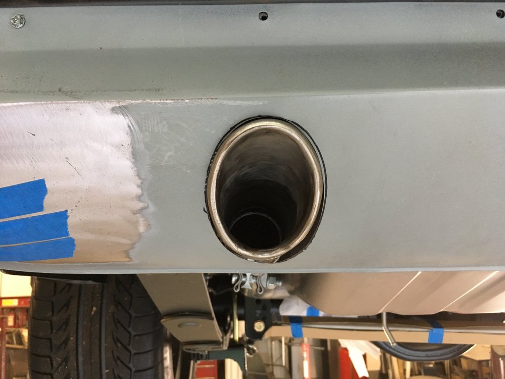
I haven't posted much of the progress lately due to the non-eventful nature of trimming and fitting the tips to the valance. This is the last fabrication portion of the long drawn out process, its almost done.
Once the holes were trimmed to fit around the tips I removed the valance and started turning the flange. I didn't want to flatten out the shape of the valance with a large flange, and I really didn't want to machine a hammer form, so a little notch in a piece of round rod does the trick.
Round and round... until the lip is almost 90 degrees. A little hammer and dolly work to planish out the small imperfections and it's ready to check on the car again.

Back in place with the tips clamped back to the pipes, the fab work is finally done!

I have to prep the tips for powder coating and there are a few brackets that also need some rust protection. Some bolts and nuts also need to be upgraded, since I was using what I had on hand.
Next up... marker light delete or return fuel line...
-
You can patch the lower portion of the quarter and butt weld it back in place. A little finishing of the weld inside and out, it will be good to go. The body line makes for a great place to install a new lower part. This happens to be a convertible, it doesn't have the sports roof body line.
If you're not into this type of fix, I'd replace the entire quarter, so there would be no seam at all on the inside. This would also go well with your tail light panel replacement. Do not get the one-piece quarter fill in part, (quarter to tail light panel) they are a pain and do not line up good. Stick with the two piece.
-
Out of curiosity, what is your labor rate? (If I can ask that type of question)
-
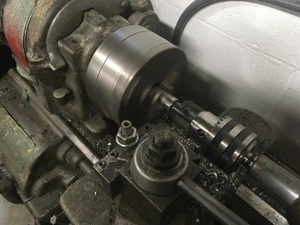
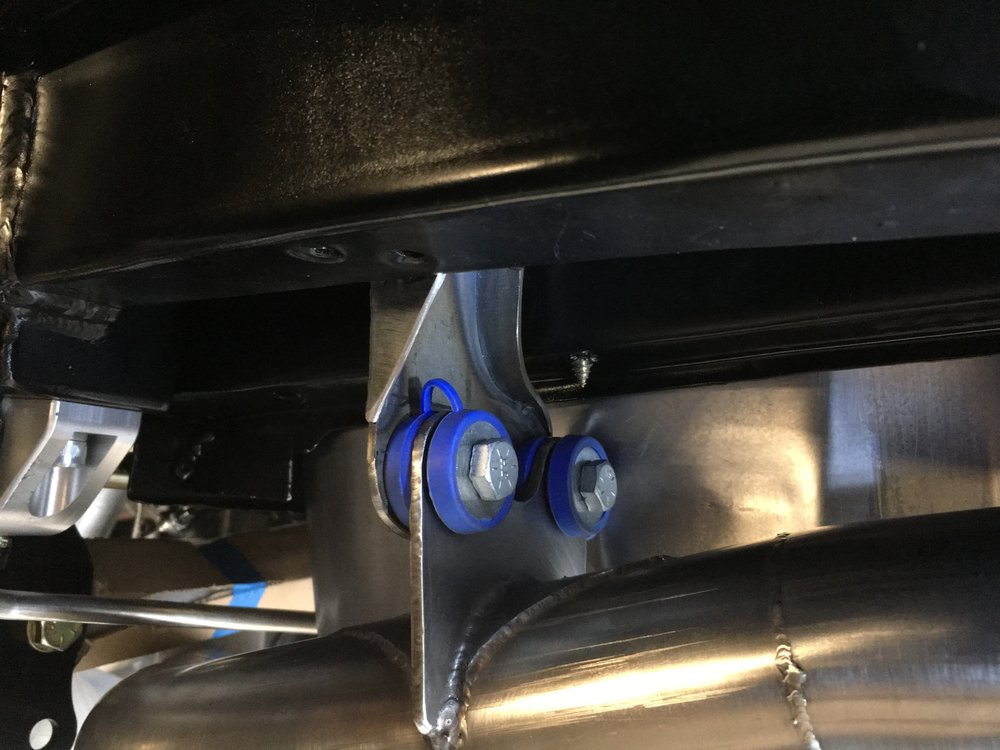
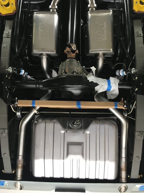
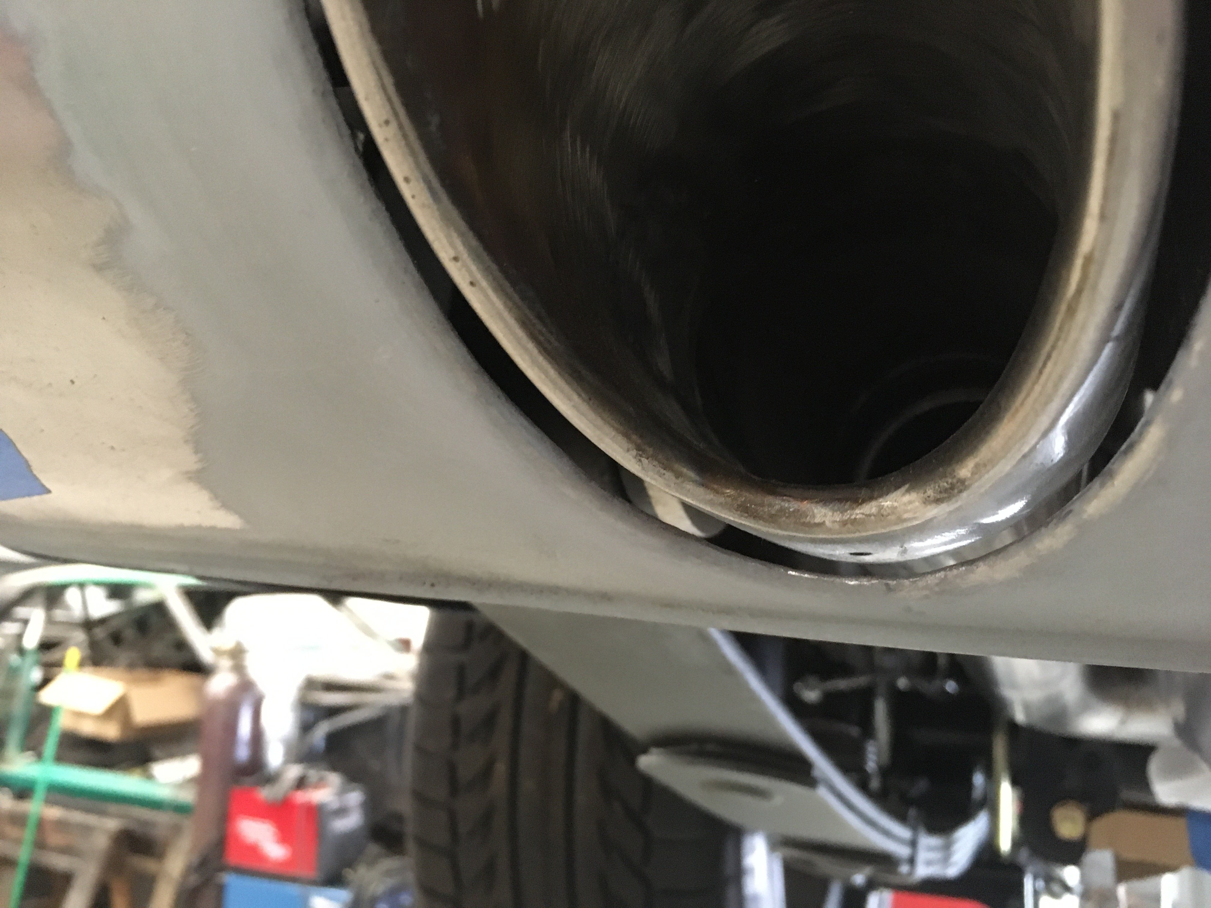
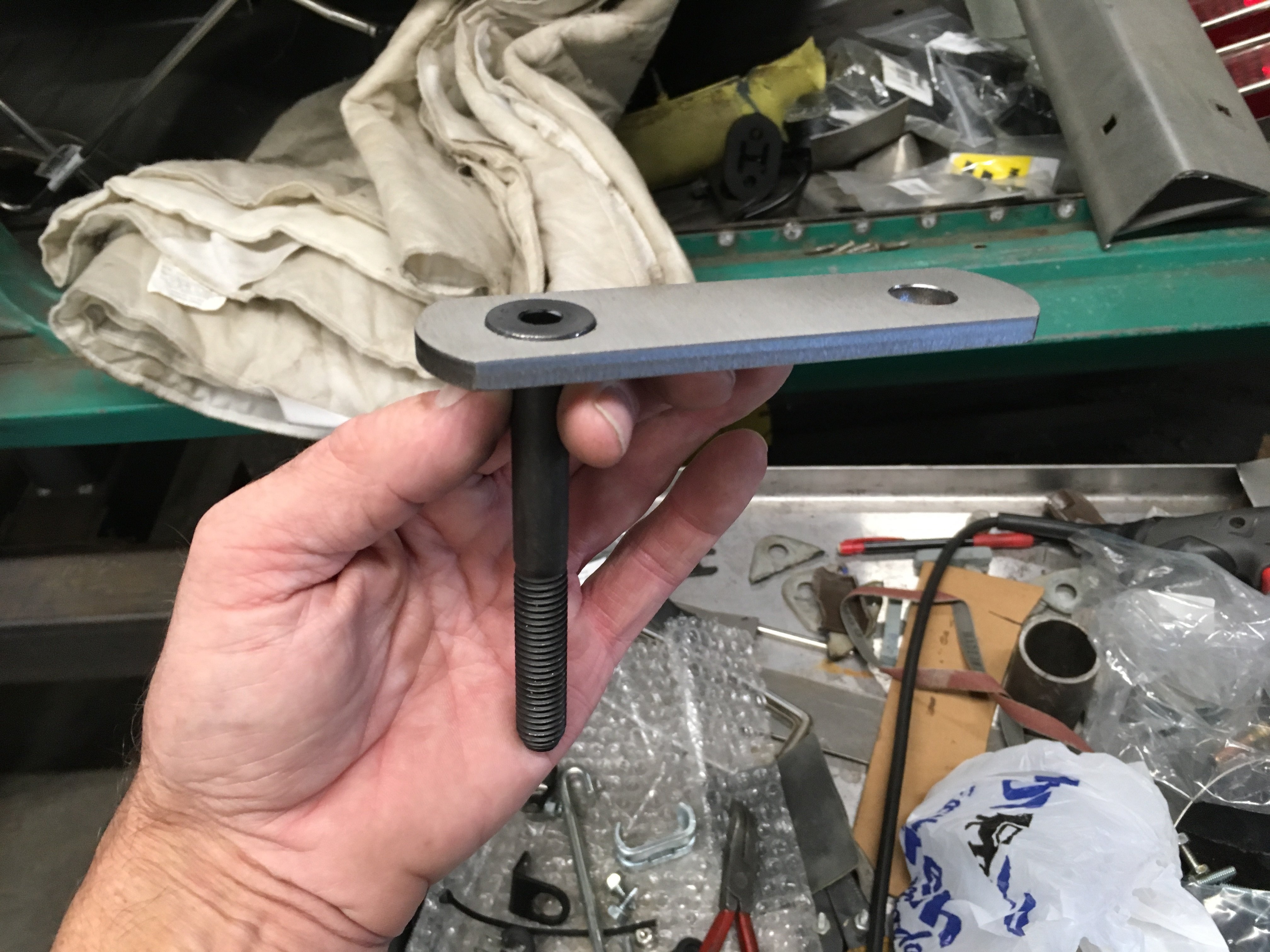
As the exhaust is finally getting close to completion, I needed to address the leaf spring shackle bolt dilemma. The head of the bolt that is supplied with the urethane bushings is large, to say the least. I notched the outer portion of the tips in the hopes that they would clear, that didn't work. I ordered some new 1/2" x 4.5" flat head bolts to help with the situation. The upgraded shackle kit has 9/16" diameter bolts and sleeves for the bushings. Since I couldn't get 9/16" flat head bolt, I needed to change up some parts. I bored some new sleeves out of 3/4" round 303 stainless with the appropriate 1/2" inside diameter and trimmed them to length.
I had some new shackle plates laser cut out of 1/4" 304 stainless, same dimensions as the kit parts, but sized for the new 1/2" lower bolt. I also countersunk 2ea of the plates to fit their new hardware.

Getting them on the car took a little bit of work to pull out the newly installed bushings and sleeves, just to stick them back together again with the new lower sleeve and upgraded hardware.
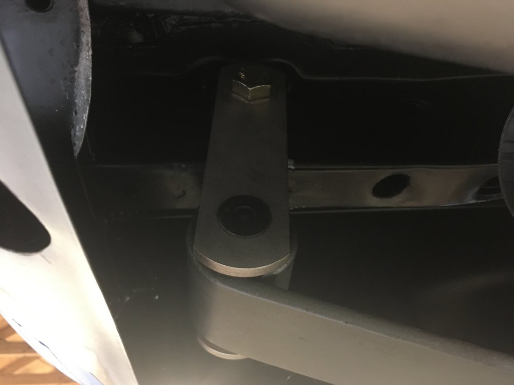
This gives approximately 3/8" clearance between the shackle and the tips. Ought to work, and they will not rust.
-
I was able to get the drive's side adjusted to where I liked it.
A little slotting of the upper bracket and all is well.
I got started on the passenger side and made good progress today. With the pan-hard bar all in the way I couldn't fit the sections without chopping and re-welding the supplied tail pipe. It wouldn't have fit anyway as it was meant to exit under the valance. A little chopping some fitting and tacking we have the second side.
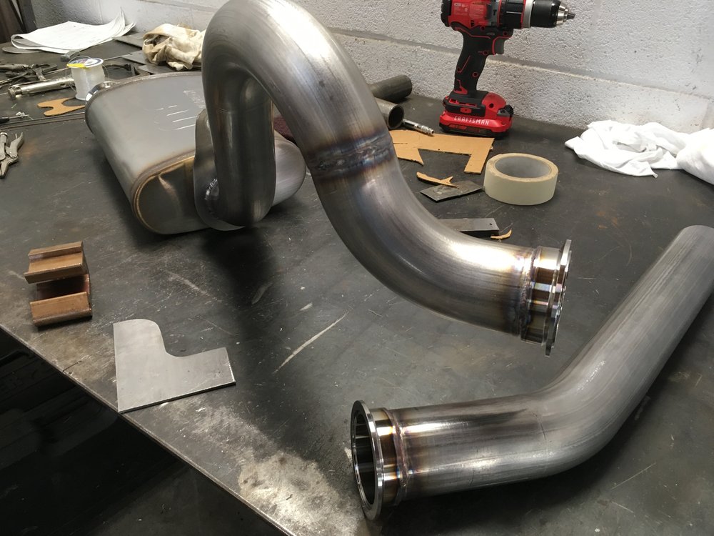
Which also receive it's fair share of red scotch-brite cleaning.
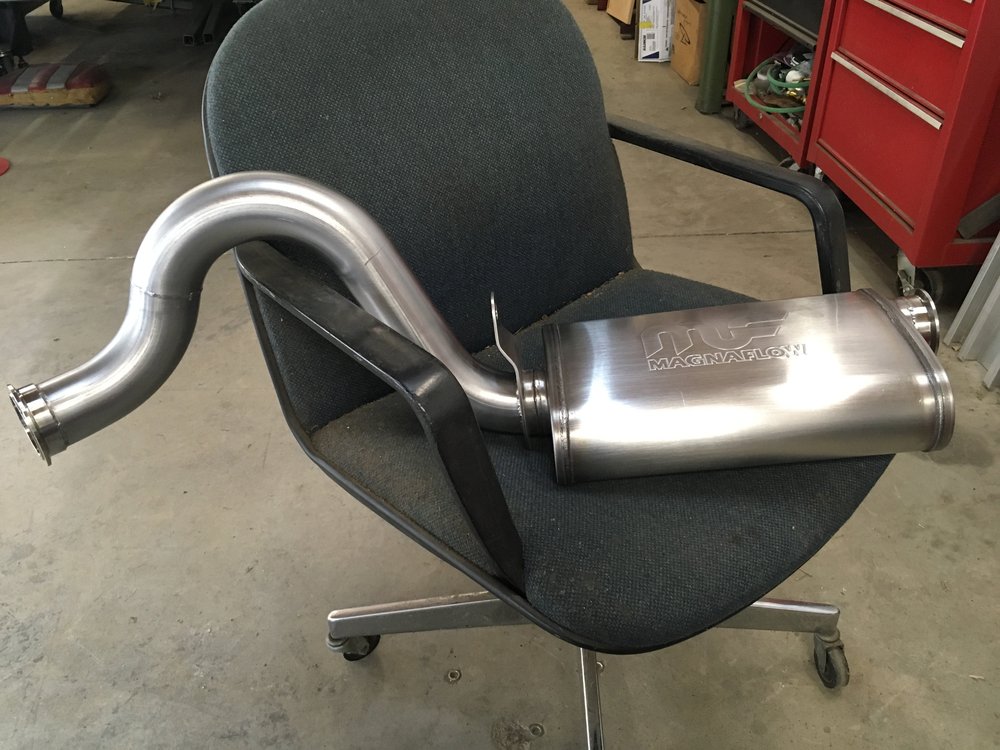
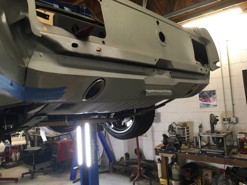
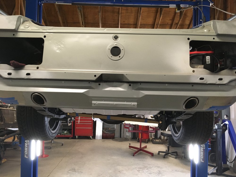
Sticking everything back under the car it looks like it should work.
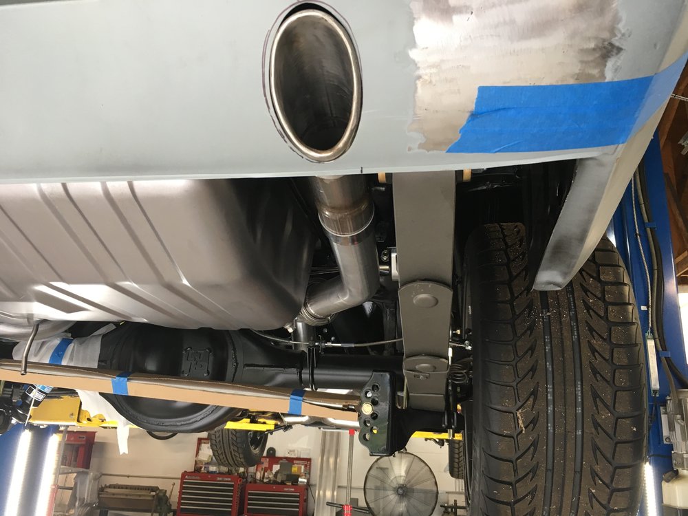
I have to remake the upper bracket on this side due to the different routing, such is life. With everything self supporting I took a picture laying on the floor looking up.
It's getting there. Least all the major components are in place, just need a few more brackets and some flanging on the valance.
Grabber70Mach reacted to this -
I edited my post to delete the "free" shipping. Haven't received any notification as of yet, but I'm sure they will be in contact with me.


Headers
in 1969-70 Technical Forum
Posted · Report reply
Just build your own. Put the tubes where you want them...