

prayers1
-
Content Count
2,112 -
Joined
-
Last visited
-
Days Won
8
Everything posted by prayers1
-

HELP! flywheel/bellhousing starter prob.
prayers1 replied to gjs14's topic in 1969-70 Technical Forum
I have a 289 4 spd toploader, 164 tooth bell and 164 tooth flywheel. Maybe you need the 164 th flywheel. I bought mine on Jegs $69.00. Have you ever had the car run with that setup? -
The thrust of this thread was to obtain information and opinions to see if I had any recourse to pursue replacement of the failed ignition parts. I received very favorable responses and received an education on wiring, both were very benificial. I have accomplished in getting the MFG. to replace the damaged items, therefore I will retire this thread and start a new regarding the ignition wiring. I want to Thank all the member in helping me, I greatly appreciate it and maybe someone who comes across this thread might find some of this information helpful as it was for me.
-
Well I went to install the HEI and the housing hits the Edelbrock 4BF Intake front runner. Then a friend lent me his which has a longer shaft, it still hits the intake. Too Bad, I really wanted that setup to work. I guess I'll have to wait for the Mallory parts to come in. I'm reluctant to use it again , for fear of a repeat incident. danno-What do you mean. Pull the connector from the ignition switch and try to turn the motor over with the solenoid/screwdriver?
-
What do you mean. Pull the connector from the ignition switch and try to turn the motor over with the solenoid/screwdriver? Good News! Here's an email form Mallory- John- I have received and processed your warranty request for the coil and modules. They should leave the factory by Monday 10/24 at the latest. Thank you, -Steve
-
Reread wiring diagram to double check things. Played with ignition terminal, pushed wires towards switch, put battery cable on, open door interio lights came on, turned key engine cranked. Stopped for now, too late at night, I'll go back to it tommorrow. I think I'll have to get one of those ignition switch pigtails. Thanks to all for responding as soon as you did. That's what I like about this site. You don't have to wait too long of a time. It's like you guys are right here. Thanks Again!
-
I pulled the ignition switch out. Saw 2 terminals with very tiny arching marks, less than a 1/16. They were not next to each other and the switch is new. T determine if I'm getting power to ignition switch, I put a test light to the heavy red wire on the back of it and ground to shifter tunnel. Nothing. I also, took the test light to the Fuse box and Shifter tunnel, Nothing! If No power to fuse BOx what else? Could it be a fuseible link. Where's it located. Double check me on solenoid wire- red/blue towards front, brown towards rear.
-
Sorry to burden you guys with my problems, but I have a MAJOR one now. Instead of waiting for Mallory to get back to me about the replacement parts, I picked up a new SBF HEI Distributor. The following was done w/o installing the HEI. I just left the Mallory Dist in with NO POWER to it. I wanted to double check TDC and needed to bump the motor. Also, the Coil has been removed. I went to turn the motor over and nothing but a click. I double checked my connections (new battery) went to do it again, as I turned the key my voltage gauge showed 12 v, interior light were on, but when I went to turn the key all the way there was a click then ZERO on the voltage gauge, in fact no power anywhere. After looking around, I thought maybe the solenoid, so I replaced it. I turned the key on, voltage gauge was 12v, then went to jump it with the solenoid, again CLICK now I hear that it’s coming form the solenoid. Now I'm not getting any power to the ignition 12v wire. No power to the headlights or interior. I did a continuity test of the brown wire from the solenoid to where it comes out of the fire wall and before attaching to the ign wire and that was good. I can turn the motor over with the solenoid (screwdriver), but not key. If I leave a test light on the ign 12v wire and the other end on the batt, the light will light up if I crank the motor with the solenoid. I even disconnected the alternator to see if any change NONE. Right now NO POWER to anything, but I can still turn the motor over with the solenoid. Does the Coil need to be hooked up to have power, I don't think so!!! FYI-NEW engine wire harness Before I did what I did today. I got in the car turned the key on and the heater motor was blowing and lower dash lights were on as well as 12v on volt gauge. Now What’s Up!!!!!!!!!!!!!
-
OK I'll let you know when it comes in.
-
Sorry to burden you guys with my problems, but I have a MAJOR one now. Instead of waiting for Mallory to get back to me about the replacement parts, I picked up a new SBF HEI Distributor. I went to start the car and nothing but a click. I double checked my connections (new battery) went to do it again, as I turned the key my voltage gauge showed 12 v, but when I went to turn the key all the way there was a click then ZERO on the voltage gauge, in fact no power anywhere. I thought maybe the solenoid, so I replaced it. I turned the key on, voltage gauge was 12v, then went to jump it with the solenoid, again CLICK now I hear that it’s coming form the solenoid. I am not getting any power to the ignition 12v wire. I did a continuity test of the brown wire from the solenoid to where it comes out of the fire wall and before attaching to the ign wire and that was good. I can turn the motor over with the solenoid, but not key. If I leave a test light on the ign 12v wire and the other end on the batt, the light will light up if I crank the motor with the solenoid. I even disconnected the alternator to see if any change NONE. Right now NO POWER to anything, but I can still turn the motor over with the solenoid. What’s Up!!!!!!!!!!!!!
-
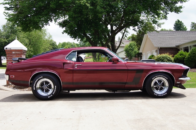
Long story short- My 1st car was a Mach 1 428 CJ, 3 speed slap stick, 4:30 rear. I it bought for $900. Only picture I have is below. At 17 yrs old, I totaled it, then went to college. So, at mid-age I bought a Fastback to try to duplicate the looks of the 1st one. I can't afford the cost of the 428 drivetrain, so the 289 4speed will do. I didn't even know about this Mustang Guy, until a friend told me about him. Wouldn't you know, he's 3 miles form me and has just about any part I would need. He has 3 warehouses full of old parts, Scott Drake, Motors, Rears & Body Panels and other stuff. He trys to be competitive but gives me a break, so I can't complain. He's a real nice Guy and will try to work with you or even trade on parts. If your looking for something, here's his info: ADCO Mustang, Eddie Adcock, 870-741-7525 I do have a test light and will look at your prior post.
-
Now I know why this wire was driving me crazy. I thought it went somewhere on the Cluster Panel. Searching on Google lead me back to this site under 69RavenConv thread. There he has a picture of its location under the ignition switch and I thought that hole was made by the PO for a toggle switch. Case Closed!
-
I'm sorry that I'm asking a ton of questions. I just don't want to have a repeat. The more I understand the better I can prevent it. I'm trying to think how the module could short out the coil. First you have to apply some white paste to the bottom of the module, Then bolt it with 2 screws to the dist. housing. Of the 3 wires coming out of the Dist. one of them is bolted to the block for ground. I appreciate your time and attention to my concern! Thank you!
-
The dash and cluster panel was already out of the dash panel when I bought the car. I installed a new Cluster Circuit Panel and Cluster Voltage Regulator. On my Fuse panel I have an Accessory Post, attached to it is a wire with 3 female ends, one of the ends has a 1.5 ft. long wire with a lightbulb at the end. This light comes on when the emergency brake pedal is pushed down. I'm trying to figure out where this bulb plugs into. I thought maybe in the cluster panel, but when I look at the only opening it says on the drivers side SEAT BELT, opposite of that hole is the light for the brake system. I had some extra Light Sockets, so I filled all of the openings in the Circuit Panel that had a circuit on it. Did I fill too many? Where does this bulb go! Heres a picture of my cluster panel circuit and accessory post wire.
-
Everything was new, even the wiring. Even though I'm just learning, the Distributor wire diagram is very easy to follow and because of my uncertainty, I spoke to Mallory techs to confirm. The Ignition wire was new coming from the KEY plug-in-terminal to Coil. If I have had to do it all over, I would wire it the same way. Hypothetically, How can a module burn out a Coil. It should be vise versa. Someone had told me about this filter. I had never used it, maybe they were thinking a resistor in-between the Dist and Coil. In the very beginning of the start up, We immediately encountered start up problems (due to the rotor). We checked voltage at the Ign wire to Pos side of Coil, Power from Coil to Dist and power to module when blocking the optic with a credit card. All checked out. What caused the 1st module to burn out. I would guess from excessive starting either causing the coil/resistor to burn out or voltage spikes. What was very obvious and wasn't there before and during our attempts to start, is when the 2nd module was installed, I then turned the key on, then placed the Pos Batt cable on the Battery. In that instance, the Batt cable krackled and the module smoked. I know this is like a Doctor trying to diagnois a problem over the telephone, but I need an logical explaination to give Mallory to warrant my parts and to prevent this from happening again. If you had to give a diffenent answer, what happened when the 2nd module was installed.
-
Congratulations on your new car! I always leave the engine rebuilding to the pros, but I've always wanted to rebuild one. That said, I would be concerned about any residule damage from a bad oil pump. If not knowing what to look for, you might be missing something that might be a warning, then you drop the motor back in and eventually you'll be pulling it for a rebulid. If I were you and the motor is already out. I would speak to a few rebuilders and get their opinion on the cheapest rebuild. You'd be better in the long run. OR This might be a good opportunity to learn about engines, so take a chance with it, by some books, look on line, ask pleanty of questions and go for it. There are a lot of great members on this site with a vast knowledge. I would replace the timing chain if anything. Good Luck to you and let us know how it's coming along
-
Are you saying that the + and - Coil terminals melted together. Is this what caused the modules to go. So, without me knowing, when I replaced the 2nd module, I figuered to test the voltage at the module by blocking the optic to see why bhe 1st went. I turned the key on and went to connect the Pos. batt. cable, it crackled and I saw the module smoke. You stated "The + and - inputs are shorted together inside the coil. If this happens, it will blow up your distributor pretty quickly. I guess you know that. " I didn't know that. Then why didn't blow up? What caused the new coil to fail. Can excessive cranking be the cause. As you may recall, I was given the wrong rotor, a 6 cyl rotor that has 6 windows instead of 8 for an 8 cyl rotor. I was cranking and cranking the motor trying to get it to start. My thinking was that the resistor failed within the coil and was sending too much voltage to the module. If I understand you correctly, the Coil went bad 1st. Is it wise on my 2nd time around, to install a filter on the Distr. red wire, right before the dist. If my understanding is wrong please advise. I need to understand why this is happening. I do appreciate your time and advise. Thank You!
-
Danno- Sorry I can't do the test light test. Yesterday, I mailed the coil and 2 modules back to Mallory for replacement. COIL- Promaster E-Coil 30450. If you copy and paste and look at Summits site, I read Primary resistence of 1.4. When I tested with the coil at it's Neg & Pos terminals, I did this with the coil disconnected on and off the vehicle body, My readings over and over were 00.2. That would indictae to me an open and full charge of 12 volts all the time. I did check the Center post to either Neg or Pos on the coil. If I'm correct that is measuring the secondary windings, I got 9.5, this is with in Mallorys range. I did my own Ohm test and it does go to ZERO. I am not that schooled in wiring, but learning a little at a time. Common sense tells me that if the Red Dist wire, & Ignition wire are joined before going to the coil that there should be 12v all the time to the module. See post #3. There are so many trains of thoughts out there. One is that the resistors in general have nothing to do with points or modules. Their only purpose is during cranking when the starter volts drop, there is no longer 12 volts at the ignition, therefore if there is a resistor tied w/in the ign wire the coil can work with 8 volts. Also, what do you think about a resistor in between the joined section of the red wire to the dist? Would that be a safe gaurd for the module. Or would it be safe to tie in a resistor at the Ignition wire. Eventually, I would like to get this Mallory Ignition system working when the replacement parts come back and I say that with my fingers crossed. I don't think Mallory should give me any problems. The Product Manager on the telephone was understanding and willing to rectify the problem. All opinions welcome!
-
Mach1Rider- I will use your advise regarding the vauge instructions if and when it comes time. Hopefully, they will replace what went bad. I've already mailed the items. Danno- Your a bit more experienced than I'm regarding wiring. I'll see if I can follow you. I did test the Coil with an Ohm meter at the neg and post coil post (00.2) mallory staes the primary wind needs to be 1.4. As for the secondary windings, placed my Volt Meter on the big center post and either neg or pos coil post. It read 9.0 which is should be per Mallory. Another question came up if a resistor would be needed if the wires are parralle or in series. This is how I ran the wires: I wired the Ign. wire directly to the RED Dist wire, then ran a single wire to the Pos. side of the Coil. Then I ran the Tach wire to the Green Dist wire, then a single wire to thye Neg side of the Coil. I'm a bit confussed, but how will the Coil Resistor protect the wires if they are wired 12v prior to the Coil. As I see it, there is no other way to do this. Before the 1st module burnt up, I did confirm 12v at the ign. and checking the module with a credit card blocking the optic I got 1.5 - 2.0. If the optic was BAD it would of read 12v. I believe excessive cranking caused the module or coil to go. Unbeknown to me the coil resistor was shot after the 1st module. I bought a 2nd and was going to test the module per Mallorys instruction video. I installed the module, turned the key on and went to put the pos battery cable on, at that moment, I heard a crackle at the battery pos post andn witness smoke coming up from the module. I checked all of my wires under the dash and in the engine are. Nothing was wrong. I concluded that since the coil was shot w/o me knowing it burnt the 2nd module. I thought of doing something different. before install the new replacement part. Getting a Duraspark Dist, a GM HEI module and a TSL Coil. Try that set up and get the motor broken in and all the bugs worked out. It's not gonna be a race car, so I'm open for suggestions. It is a 289 bored 60 over Cam has 280 duration & 512 lift, 54cc Head w/screw in studs & 194 GM valves, Dual plane Ebelbrock FB4 manifold, 600 Holley DP, 4 speed toploader, 3:55 9' traction lok Sorry typed in a hurry, didn't check spelling!!!!!!!
-
I agree with you. The question has come up on installing a resistor on the red wire going to the distributor, but someone had said it doesn't matter how much current the module sees it's the voltage spikes that kills the modules. I think the coil resistor is to protect the coil, and I think everyone thinks it protects the module. I'm a little confused myself. I contacted Mallory this morning. They said to forward the wrong rotor and damaged items for replacement. Will see if they keep their word.
-
I'm really ticked about this. I've been trying to be mindful on my budget to get things done right the first time, so I ask a ton of questions, not for some Company package mixup to cost me more. After consulting with Mallory, here's what they told me on how to wire the Dist & Coil. Splice together the 12v from Ignition to Red wire from Dist-then run a wire to the Pos. side of the coil. Take Green wire from Dist and green wire from Tach, tie them together and runa wire to the Neg. side of the coil. Brown wire frm Dist. to GOOD engine ground. My theroy is that from cranking the motor over too long with the wrong rotor shutter wheel, it eventually over heated the Coil and burnt the resistor in it, this allowed a direct 12v source to the Module. Before installing the 2nd module, I checked for current and had 12 v to the coil with the key on . Then after installing the 2nd Module, I went to check voltage at the module, this is done by turning the key on and you placing a credit card inbetween the optic eye, you should get a 1.5 -2.0 v reading (if 12v it's shot), but when I went to do that, the key needed to be on which it was, then I was to put the pos. Battery cable on, as soon as I did that it smoked before I placed the credit card there. To confirm the Module now reads 12v. Someone told me that it doesn't matter on the Dist red wire side if the coil had a resistor or not, that a Res. shoud of been between the Dist. and Coil. Then why would the coil ohms read on the Primary side 00.2 instead of 1.4. I respect everyone's opinion, so chime in with yours, because I'm looking for the best logical explaination when I call Mallory tomorrow. Here's a copy of the module instructions. You can see they say no need for a resistor if using Coil 304540.
-
I bought Mallory Unilite distributor & a Promaster E-coil (internal resister). I switched the ignition Pink wire to 12 volts. I spoke to several Mallory techs who helped me decide on how to wire this system under the hood & what spark plug wires to use. Installation is very basic, Ignition 12v wire to Pos. side of coil and to red wire on Distributor, Green wire from Dist to neg side of coil, Dist brown wire to GOOD engine ground. That's it! Since I had an E-Coil, I bought from Jegs a new Mallory Male end Dist cap & rotor and MSD spark plug wires. I installed a rebuilt 289 and 4 speed toploader. Basically everything under the hood is NEW. We went to do the first run and couldn't get the motor to fire up, it kept back firing and sometimes pretty bad. We went through the basics spark, air & gas and couldn't find anything wrong. We checked Voltage at the coil and even did the module test per Mallory's website and everything was fine. We kept trying to change timing over and over again. Finally we went to see if the Dist Cap or rotor was cracked and found that the rotor had 6 slots for the optic viewing instead of 8. After getting the correct rotor we now find that the module is burnt. I got another module locally for $130, installed it and it went up in SMOKE. We did the module test and it showed 12 v instead of 1.5-2.0 (Bad Module again). We checked the coil ignition and dist side and getting 12 volts. Then we did an ohm's test on the Neg & Pos side of the coil (Primary windings)and it showed 00.2 instead of the factory 1.4. We also checked the secondary windings which was within the factory range of 9.0. We concluded that by trying to start the motor over and over many times, that it somehow burnt the resistor in the coil leaving an open current and each time a new module was put in it would burn out. I contacted Jegs and they said that they would replace the rotor with the right one but my beef about other stuff lies with Mallory. I believe that if I had the right rotor to begin with that no of this would of happened. I would like if Mallory would replace the coil and module, but how do I explain it in terms to be benifical to my cause. As we know the Big Companies can talk their way out of anything, since they are the experts and I am just a weekend mechanic. Any SERIOUS susgestions and Please dont say "shouldn't of bought a Mallory" Thanks for your help, John
-
I installed the volt gauge to it and it works fine, since it is keyed on power. There is a green factory wire attached to the assy post with a bulb at the end for the E Brak. I know because, when I put on the Emergency brake the light lites up.
-
69gmachine- Are you saying that I can hook up my mechanical volt meter to this post. If so, do I install a inline fuse. It is tied into fuse #2, 20 amp. This harness is not the original, as mine was butchered by the PO. I bought this off eBay, it was a direct fit. I don't think it has the Tach wiring.
-
Here's what I'm talking about
-
What is the Accessory Post on the inside fuse panel for. Mine and I assume all 69's have a 3 female prog with one center line connected to a light bulb. Where does that bulb go to and can I use that acc post to power a Tach or a 12 volt supply for volt meter.